G43UF / Page 5
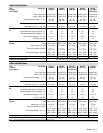
SPECIFICATIONS
Gas
Heating
Performance
ModelNo. G43UF
−24B−045
G43UF
−24B−070
G43UF
−36B−070
G43UF
−36C−090
G43UF
−36C−090H
Canada Only
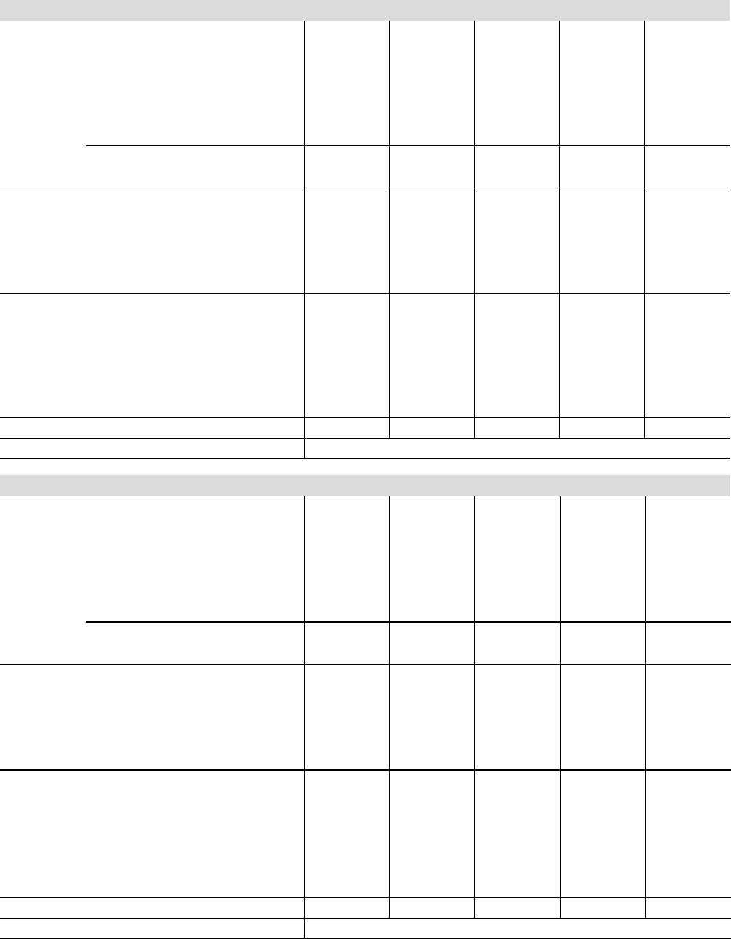
Input− Btuh (kW) 44,000 (12.9) 66,000 (19.3) 66,000 (19.3) 88,000 (25.8) 88,000 (25.8)
Output− Btuh (kW) 40,300 (11.8) 61,000 (17.9) 62,000 (18.2) 82,000 (24.0) 81,000 (23.7)
Temperature rise range − _F (_C) 30 − 60
(18 − 36)
50 − 80
(28 − 44)
40 − 70
(22 − 39)
40 − 70
(22 − 39)
50 − 80
(28 − 44)
1
AFUE 92.1% 90.0% 92.1% 92.1% 90.0%
Highstatic(CSA)− in.w.g. (Pa) .50 (124) .50 (124) .50 (124) .50 (124) .50 (124)
Connections
in
Intake / Exhaust Pipe (PVC) 2 / 2 2 / 2 2 / 2 2 / 2 2 / 2
in.
Condensate Drain Trap (PVC pipe) − i.d. 1/2 1/2 1/2 1/2 1/2
with field supplied (PVC coupling) − o.d. 3/4 3/4 3/4 3/4 3/4
hose with hose clamp − i.d. x o.d. 1−1/4 x 1 1−1/4 x 1 1−1/4 x 1 1−1/4 x 1 1−1/4 x 1
GaspipesizeIPS 1/2 1/2 1/2 1/2 1/2
Indoor
Blower
Wheel nominal diameter x width −in.
(mm)
10 x 7
(254 x 178)
10 x 7
(254 x 178)
10 x 8
(254 x 203)
10 x 8
(254 x 203)
10 x 8
(254 x 203)
Motoroutput − hp (W) 1/5 (149) 1/5 (149) 1/3 (249) 1/3 (249) 1/3 (249)
Tons(kW) ofadd−oncooling 1.5 − 2
(5.3 − 7.0)
1.5 − 2
(5.3 − 7.0)
2 − 3
(8.8 − 10.5)
2 − 3
(7.0 − 10.5)
2 − 3
(7.0 − 10.5)
Air Volume Range − cfm (L/s) 465 − 1125
(220 − 530)
425 − 1020
(200 − 480)
710 − 1640
(335 − 775)
730 − 1630
(345 − 770)
730 − 1630
(345 − 770)
ShippingData − lbs. (kg) − 1 package 132 (60) 141 (64) 146 (66) 162 (74) 162 (74)
Electricalcharacteristics 120 volts − 60 hertz − 1 phase (less than 12 amps)
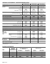
SPECIFICATIONS
Gas
Heating
Performance
ModelNo.
G43UF
−48C−090
G43UF
−48C−110
G43UF
−48C−110H
Canada Only
G43UF
−60C−110
G43UF
−60D−135
Input− Btuh (kW) 88,000 (25.8) 110,000 (32.2) 110,000 (32.2) 110,000 (32.2) 132,000 (38.7)
Output− Btuh (kW) 82,000 (24.0) 103,000 (30.2) 101,000 (29.6) 103,000 (30.2) 123,000 (36.0)
Temperature rise range − _F (_C) 40 − 70
(22 − 39)
45 − 75
(27 − 45)
50 − 80
(28 − 44)
40 − 70
(22 − 39)
45 − 75
(27 − 45)
1
AFUE 92.1% 92.1% 90.0% 92.1% 92.1%
Highstatic(CSA)− in.w.g. (Pa) .50 (124) .50 (124) .50 (124) .50 (124) .50 (124)
Connections
in
Intake / Exhaust Pipe (PVC) 2 / 2 2 / 2 2 / 2 2 / 2 3 / 3
in.
Condensate Drain Trap (PVC pipe) − i.d.
1/2 1/2 1/2 1/2 1/2
with field supplied (PVC coupling) − o.d. 3/4 3/4 3/4 3/4 3/4
hose with hose clamp − i.d. x o.d. 1−1/4 x 1 1−1/4 x 1 1−1/4 x 1 1−1/4 x 1 1−1/4 x 1
GaspipesizeIPS 1/2 1/2 1/2 1/2 1/2
Indoor
Blower
Wheelnominaldiameter xwidth −in.
(mm)
10 x 10
(254 x 254)
10 x 10
(254 x 254)
10 x 10
(254 x 254)
11−1/2 x 10
(292 x 229)
11−1/2 x 10
(292 x 229)
Motoroutput − hp (W) 1/2 (373) 1/2 (373) 1/2 (373) 1 (746) 1 (746)
Tons(kW) ofadd−oncooling 3 − 4
(10.5 − 14.0)
3 − 4
(10.5 − 14.0)
3 − 4
(10.5 − 14.0)
4 − 5
(14.0 − 17.5)
4 − 5
(14.0 − 17.5)
Air Volume Range − cfm (L/s) 950 − 2180
(450 − 1030)
885 − 2160
(420 − 1020)
885 − 2160
(420 − 1020)
1470 − 2720
(695 − 1285)
1440 − 2730
(680 − 1290)
ShippingData − lbs. (kg) − 1 package 168 (76) 178 (81) 178 (81) 186 (84) 203 (92)
Electricalcharacteristics 120 volts − 60 hertz − 1 phase (less than 12 amps)
NOTE − Filters and provisions for mounting are not furnished and must be field provided.
1
Annual Fuel Utilization Efficiency based on DOE test procedures and according to FTC labeling regulations. Isolated combustion system rating for non−weatherized furnaces


