


Step 9. Turn on gas supply and test for gas leaks using a gas leak test
solution (see Test Procedure on Page 11 in the Installation and
Operation Manual).
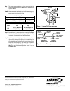
Step 10. Using a manometer, test the inlet and manifold gas pressure per
instructions in the Installation and Operation Manual (Page 11)
and as shown in the following 2 tables.
Step 11. Reinstall the the log set and glass door assembly. See Pages
9 and 10 (Log Set Installation) and Page 18 (Door Assembly
Installation) in the Installation and Operation Manual.
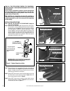
Step 12. Light the appliance per the lighting instructions label on appliance
(when viewing the insert from the front, it is located behind the
right side door, on the right) or lighting instructions on Page 13
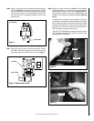
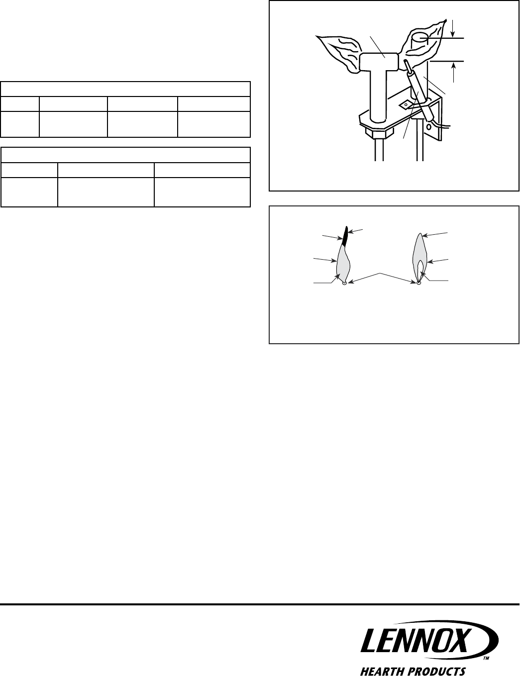
in the Installation and Operation Manual. Inspect for proper pilot
and burner flame appearances. See Flame Color and Behavior
on Page 14 and Inspect The Pilot System For Proper Flame on
Page 16 in the Installation and Operation Manual. Also see
Figures 12 and 13.
Figure 13 - Burner Flame Appearance
No Blue Flame
Center
Soot at
Flame Tip
Dark Orange
Flame
IMPROPERLY
BURNING FLAME
Soot above
Flame Tip
No Soot at
Flame Tip
PROPERLY
BURNING FLAME
Semi-Transparent
Yellow Flame
Blue Flame
Center
Ports on Pan
Burner Assembly
Figure 12 - Proper Pilot Flame Appearance
Millivolt Pilot
Thermopile
Igniter
Gas Pilot Hood
3/8” to
1/2”
Inlet Gas Supply Pressure
Fuel # Minimum Maximum Desired
LP
10.5" WC/po. C.E
(2.62 kPa)
13.0" WC/po. C.E
(3.23 kPa)
11" WC/po. C.E
(2.74 kPa)
Manifold Gas Supply Pressure
Fuel # Low High
LP
(Lo) 5.4" WC/po. C.E
(1.35 kPa)
(Hi) 10.0" WC/po. C.E
(2.49 kPa)
Printed in U.S.A. © 2008 Lennox Hearth Products
P/N 775,251M REV. A 09/2008
Lennox Hearth Products reserves the right to make changes at any time, without notice, in
design, materials, specifications, prices and also to discontinue colors, styles and products.
Consult your local distributor for fireplace code information.
1110 West Taft Avenue • Orange, CA 92865
4