


NOTE: DIAGRAMS & ILLUSTRATIONS ARE NOT TO SCALE.
20
LENNOX HEARTH PRODUCTS • ESTATE™ SERIES WOOD-BURNING FIREPLACES • MODELS EST-36, EST-42, EST-50 • INSTALLATION INSTRUCTIONS
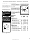
GAS LINE CONNECTION
The Estate Series fireplaces have been approved
to accept a 1/2" (13 mm) gas line for an ap-
proved gas appliance. Always have the appliance
installed by a qualified, licensed plumber in
accordance with all local building codes. The
gas line may enter either side of the fireplace.
CAUTION: PLUMBING CONNECTIONS SHOULD
ONLY BE PERFORMED BY A QUALIFIED,
LICENSED PLUMBER. MAIN GAS SUPPLY
MUST BE OFF WHEN PLUMBING GAS LINE
TO FIREPLACE OR PERFORMING SERVICE.
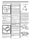
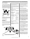
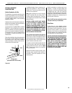
If you’re installing a gas line, connect it before the
fireplace is framed and enclosed in the finished
wall. The gas knockout is determined by a 1-1/8"
(29 mm) round indentation located at the bottom
and slightly off center in the side refractories.
THE KNOCKOUT IS ALWAYS REMOVED FROM
INSIDE THE FIREPLACE. DO NOT REMOVE THE
KNOCKOUT UNLESS YOU ARE INSTALLING A
GAS LINE. If removal is attempted from the
outer wrapper, side-refractory damage may
occur. With a medium-sized hammer, lightly tap
the surface of the indentation. The refractory
material is very thin in this area and is easily
removed. Once a small hole has been made,
continue tapping until you have reached suffi-
cient diameter for the gas line to fit through. The
entire knockout does not have to be removed.
Remove insulation in the gas line channel.
Install a 1/2" (13 mm) gas supply line through
fireplace wall for connection to a decorative
gas appliance inside the rebox. Outside, the
gas supply line connects to a gas shut-off valve
recessed flush into the wall or floor. The valve
should be controlled by a removable valve key
for safety.
Always plumb gas line installation per local
codes. Check all connections with soap suds;
leaks will bubble. Never test any gas line con-
nection with a match or open flame.
IMPORTANT: RE-PACK INSULATION MATE-
RIAL IN SQUARE HOLE AROUND GAS LINE;
INTERIOR AND EXTERIOR, TO SEAL.
This provision is intended only for connection
to a decorative gas appliance incorporating an
automatic shut-off device and complying with
the standard for Decorative Gas Appliances for
installation in vented fireplaces, ANSI Z21.60.
Install in accordance with the National Fuel
Gas Code, ANSI Z223.1. This complies with
the revised U.L. 127 standard.
CAUTION: WHEN USING THE DECORATIVE
GAS APPLIANCE, THE FIREPLACE DAMPER
MUST BE SET IN THE FULLY OPEN POSITION.
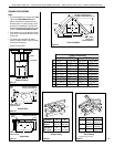
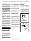
Vent Free Appliances
These units have been tested and approved to
ANSI/IAS/AGA Z21.11.2 for use with unvented
gas appliances and complies with the standard
for Factory-Built replaces, UL 127.
The unit has been tested for use with any unvented
gas log sets having a maximum rating of 40,000
BTU. The minimum mantel congurations are
outlined in Figures 45 and 46.
These fireplaces have been marked with a
maximum rating of 40,000 BTU to assure that
homeowners do not exceed the allowable limits
for all allowed installations of mantels.
NEVER INSTALL AN UNVENTED GAS LOG SET
WITH A BTU GREATER THAN 40,000.
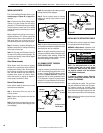
COLD CLIMATE INSULATION
If you live in a cold climate, it is especially
important to seal all cracks around the fire-
place opening with noncombustible material
and wherever cold air could enter the room.
Surrounding materials must be caulked where
it meets the black metal facing of the fireplace
to avoid cold air intrusion. Use noncombustible
caulking material only on fireplace facing to
seal. Also, the outside air inlet duct should be
wrapped with noncombustible insulation to
minimize the formation of condensation. Do
not place insulation materials against chimney
sections.
Note: A 2" (51 mm) air space must be preserved
for all combustible materials extending for any
continuous length adjacent to the chimney.
It is especially important to insulate between the
studs of an outside chase cavity and under the
floor if the floor is above ground level. Do not
place insulation directly against the fireplace
or chimney system.
FIREPLACE FINISHES
Mantels and Trim
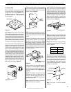
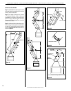
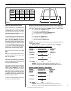
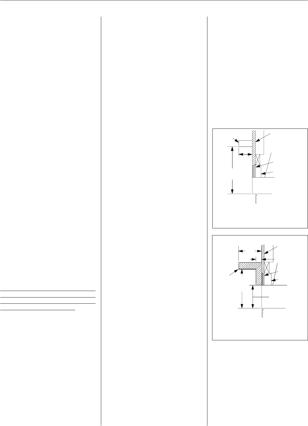
In Canada, the minimum height for a combus-
tible mantel is 24" (610 mm) above the fireplace
opening (EST-36 and EST-42 only). Figure 45
shows a typical Canadian installation.
NOTE: The EST-50 is not for use in Canada.
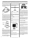
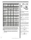
In the U.S., combustible mantels and trim
may be installed as shown in Figure 46 as per
NFPA 211-Mantel/Trim Clearances. If a mantel
is of a noncombustible material, it is exempt
from these requirements, as long as it does
not interfere with the installation or operation
of glass doors.
Combustible
Mantel
Spacer
Noncombustible
Wall Covering
Finished
Wall
Canadian Installation
(36 and 42 models only)
Fireplace
Opening
Facing
Flush
24" Min.
(610mm)
8" Max.
(203mm)
Figure 45
Figure 46
Typical Canadian Installation
(EST-36 and EST-42 only)
Fireplace
Opening
EST-36 & EST-42:
6-9/16" (167mm)
EST-50:
10" (254mm)
12"
(305mm)
Min.
Combustible
Mantel
and Trim
Spacer
Noncombustible
Wall Covering
Finished
Wall
12"
(305mm)
Max.
1-1/2" (38mm)
FIREPLACE FINISHES:
Mantels and Trim
In installations other than Canada, combustible mantels
and trim may be installed as shown in the illustrations
below and as per NFPA 211-Mantel/Trim Clearances. If a
mantel is of a noncombustible material, it is exempt from
these requirements as long as it does NOT interfere with
the installation or operation of glass doors.
For combustible mantel and trim specifications in
Canadian installations (EST-36 and EST-42 only), see
the fireplace Installation Instructions.
Typical U.S. Installation