


NOTE: DIAGRAMS & ILLUSTRATIONS ARE NOT TO SCALE.
12
LENNOX HEARTH PRODUCTS • ESTATE™ SERIES WOOD-BURNING FIREPLACES • MODELS EST-36, EST-42, EST-50 • INSTALLATION INSTRUCTIONS
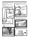
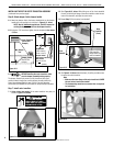
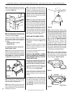
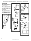
Step 5. Secure the fireplace to the side framing
members using the nailing flange. Use 8d nails
or equivalent (Figure 18).
Note: The nailing flange and the area directly
behind the nailing flange are exempt from the
clearances described on page 5.
Maintain the following minimum clearance
from the firebox wrapper to the framing at the
closest point of contact, directly adjacent to
the flange:
• EST-36 and EST-42: 1/2" min.
• EST-50: 3/4" min.
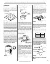
For installations in Canada, continue with
Steps 6 through 9, below.
Step 6. Remove one of the knockouts from the
fireplace transition and attach the 4" (102 mm)
collar from the Cold Climate Kit to the transition
with four (4) No. 8 x 1/2" screws provided (Fig-
ure 19, below). See “Installation Components”
on page 24 for catalog/part numbers.
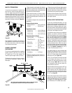
Figure 20
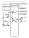
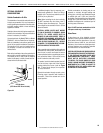
Step 3. Position appropriate firestop spacer
at ceiling and nail temporarily with two (2) 8d
nails. Use at restop spacer, Model F10FS-2, if
chimney penetrates ceiling vertically. If chimney
penetrates ceiling at 30° angle (offset chimney),
use 30° restop spacer, Model F10FS30-2
(refer to “30° Chimney Offset through
Floor or Ceiling” and Figures 42 and 43 on
page 18). Use one nail on opposite sides
to hold firestop spacer in position. Nail
permanently, using at least two (2) more
8d nails, after chimney sections have been
assembled through the firestop spacer and after
any necessary adjustments have been made.
Firestop spacer must be secured by at least four
(4) 8d nails when completely installed.
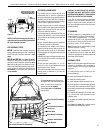
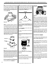
Note: If there is a room above ceiling level,
firestop spacer must be installed on the bottom
side of the ceiling. If an attic is above ceiling
level, firestop spacer must be installed on top
side of ceiling joist (Figures 21 and 22).
Firestop Spacer
Room Above
Firestop Spacer
Attic Above
Figure 22
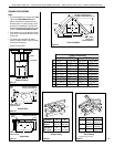
Note: If the fireplace is installed against an
inside wall, the Class 0 air duct may be ex-
tended into a ventilated attic space at least 18"
(457 mm) above the attic floor. Secure the duct
hood to a vertical post with the inlet positioned
downward. Ensure nothing blocks the hood
opening. This air duct must never terminate
higher than the chimney.
Step 9. Cut or frame hole through the outside
wall for the installation of the duct inlet hood.
A 4-1/2" (114 mm) diameter hole is sufficient.
Feed the loose end of the exible duct through
the hole cut for the inlet hood and attach to
collar on inlet hood using two (2) No. 6 x 3/8"
screws provided. Insert hood into opening.
Secure hood in place with the No. 8 x 1-1/2"
screws provided or with nails driven through
holes in hood flange. Seal with noncombustible
waterproof silicon type caulking. If additional
duct is needed, use Class 0 metallic duct.
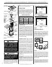
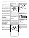
INSTALLING THE CHIMNEY SYSTEM
Step 1. Before continuing, check the operation
of the damper, as described on page 4, (refer
to Figure 3).
Step 2. Using standard construction framing
techniques, construct opening for chimney
route up through the ceiling(s) and roof or
through an outside chase.
Framing must maintain adequate minimum air
space clearance at all times.
CAUTION: ALLOW MINIMUM 2" CHIMNEY
AIR SPACE TO COMBUSTIBLE FRAMING MEM-
BERS THROUGHOUT VERTICAL OR OFFSET
CHIMNEY INSTALLATION.
A minimum 2" air space must be reserved for
all combustible materials extending for any
continuous length surrounding the chimney.
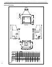
For minimum ceiling and roof dimensions, see
Figure 16 (Ceiling Framing) and Figure 17
(Roof Framing) on the previous page.
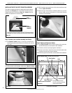
In new construction, to determine chimney
center line, use plumb line from roof or ceil-
ing above fireplace to center of flue collar on
fireplace.
For remodeling, plumb to center of ue collar
from ceiling above, drive nail through ceiling
from below to mark position, then mark and
cut to passage from above ceiling (around
nail) (Figure 20). Then plumb from ceiling or
roof level directly above hole which has just
been completed.
(Optional
Position)
Cold Climate Kit
(Canada only)
Step 7. Connect the 4" (102 mm) Class 0 air
duct to the collar with two (2) No. 8 x 1/2"
screws provided in the hardware kit.
Step 8. Route the Class 0 air duct out the back
wall or side wall, up through the ceiling or floor
joists to an outside wall. The air duct should be
located above snow level.
Plumb Line
Figure 21
Figure 19
Nailing
Flange
Framing
Stud
8d Nail
Figure 18