


4
NOTE: DIAGRAMS & ILLUSTRATIONS NOT TO SCALE.
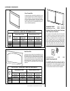
Glass Enclosure Panels - Removal and
Installation.
CAUTION: DO NOT TOUCH THE FRONT EN-
CLOSURE GLASS WITH YOUR HANDS WHILE
THE FIREPLACE IS IN USE.
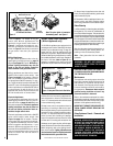
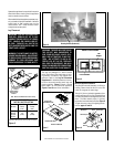
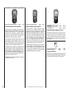
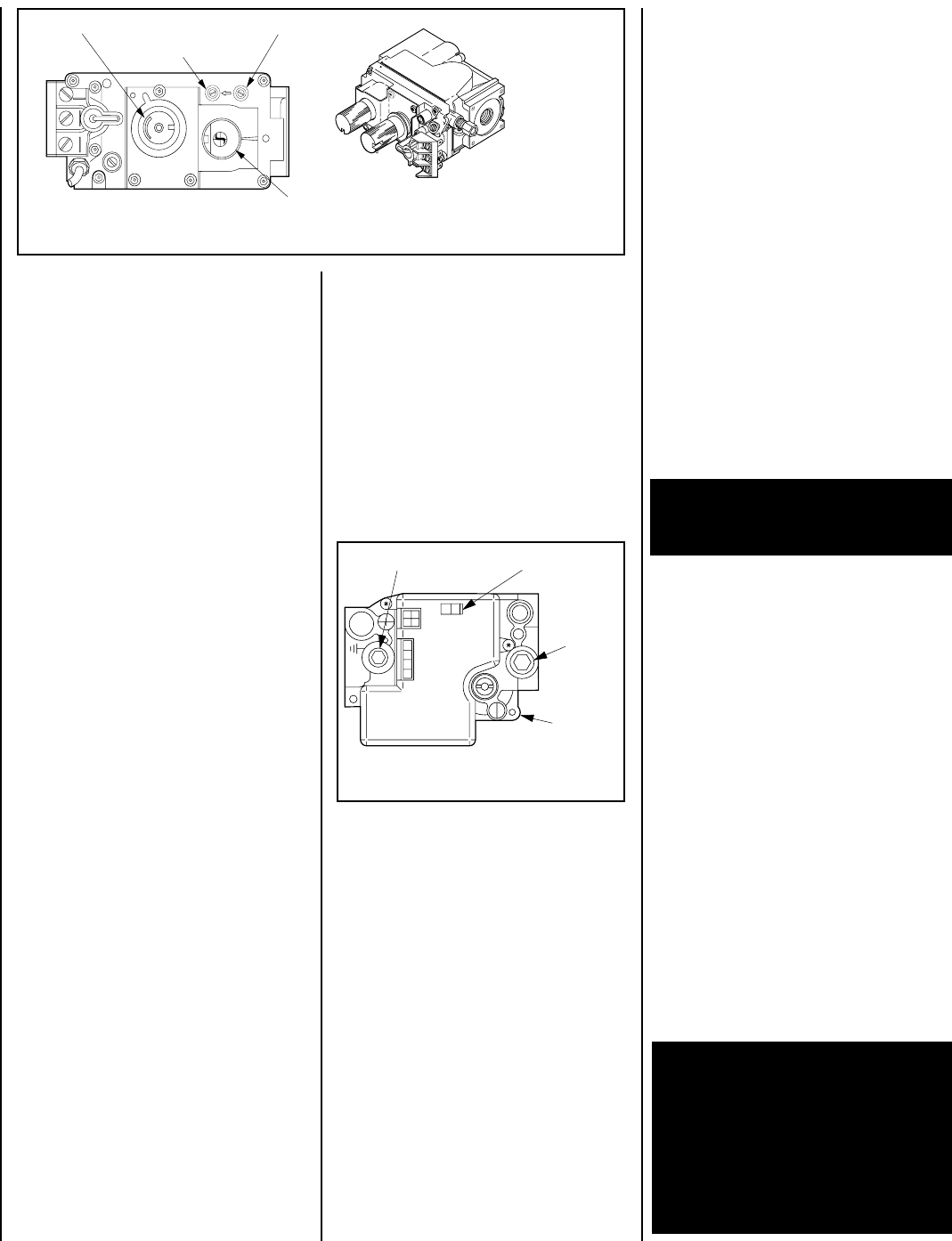
Figure 3 Honeywell Electronic Gas Valve
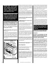
2. When lit for the first time, this appliance will
emit a slight odor for 14 hours. This is due to the
“burn-in” of internal paints and lubricants used
in the manufacturing process.
3. Keep lower control compartment clean by
vacuuming or brushing at least twice a year.
More frequent cleaning may be required due to
excessive lint from carpeting, bedding materi-
als, etc. It is important that control compart-
ments, burners and circulating air passage-
ways of the appliance be kept clean and clear
of obstruction of venting and combustion air.
4. Always turn off gas to the pilot (millivolt appli-
ances) and let the unit cool down before cleaning.
Before re-lighting, refer to the lighting instruc-
tions in this manual. Lighting instructions may
also be found on the pull out lighting instruction
labels attached to the gas control valve.
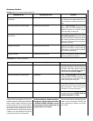
Maintenance
The appliance and venting system should be
thoroughly inspected before initial use and at
least annually by a qualified service techni-
cian. However, more frequent periodic inspec-
tions and cleanings should be performed by
the homeowner. Homeowner must contact a
qualified service technician at once if any
abnormal condition is observed.
Refer to the maintenance schedule for mainte-
nance tasks, procedures, periodicity and by whom
they should be performed. Always verify proper
operation of the appliance after servicing.
IMPORTANT: TURN OFF GAS AND ANY ELEC-
TRICAL POWER BEFORE SERVICING THE
APPLIANCE.
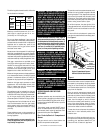
Figure 2
Note: The piezo ignitor is located on
the modesty panel - see Figure 1.
After that the glass should be cleaned two or
three times during each heating season, de-
pending on the circumstances present.
Note: Clean glass after first two weeks of
operation.
ON/OFF Switch
Electronic
Gas Control
Valve
Inlet
Pressure
Port
Manifold Pressure Port
OFF
IN
P
S
I
ON
CONTROL
IG
N
IT
E
R
WARNING: DO NOT USE ABRASIVE
CLEANERS. NEVER CLEAN THE GLASS
WHEN IT IS HOT.
WARNING: NEVER OPERATE THE APPLIANCE
WITHOUT THE GLASS ENCLOSURE PANELS
IN PLACE AND SECURE. DO NOT OPERATE
APPLIANCE WITH ANY OF THE GLASS PAN-
ELS CRACKED, BROKEN OR MISSING. RE-
PLACEMENT PANELS ARE AVAILABLE
THROUGH YOUR LOCAL LENNOX DEALER
AND MUST BE INSTALLED BY A LICENSED OR
QUALIFIED SERVICE TECHNICIAN.
H
I
L
O
W
TPTH TP TH
P
I
L
O
T
P
I
L
O
T
O
N
it
O
F
F
Variable Flame Height Adjustment
Manifold Pressure Port
Inlet Pressure Port
Main Gas
Control Knob
IN
OUT
SIT Millivolt Gas Valve
5. Always keep the appliance area clear and
free from combustible materials, gasoline and
other flammable liquids.
6. Remember, Millivolt appliances have a con-
tinuous burning pilot flame. Exercise caution
when using products with combustible vapors.
Glass Cleaning
It will be necessary to clean the glass periodically.
During start-up it is normal for condensation to
form on the inside of the glass. This can cause lint,
dust and other airborne particles to cling to the glass
surface. Also initial paint curing may deposit a slight
film on the glass. It is therefore recommended that
the glass be cleaned two or three times with a non-
ammonia household cleaner and warm water (a gas
fireplace glass cleaner is recommended).
Variable Flame Height Adjustment
( Millivolt Appliances only)
1. All Millivolt appliances are equipped with a
variable gas control valve. Flame height for these
models may be adjusted through a range be-
tween fixed low and high settings while the
appliance is in operation. Adjust the flame height
as desired after lighting the appliance by rotating
the variable adjustment control knob located on
the front of the valve
(refer to Figure 2)
. (An
extension is attached to this knob so that the
adjustment may be made at the modesty panel.)
Refer to Figure 1
for access to the gas
control valve. Millivolt appliances will be
fitted with the gas control valve shown in
Figure 2
. Appliances with electronic sys-
tems will be fitted with the electronic valve
shown in
Figure 3
. Familiarize yourself with
the gas control valve that your appliance
uses.
Millivolt Appliances -
To light millivolt appliances refer to the de-
tailed lighting instructions found on
page 12
(English) and page 13
(French). Millivolt ap-
pliance lighting instructions may also be
found on the pull out lighting instruction
labels attached to the gas control valve.
Millivolt appliances are fitted with a burner
ON/OFF control switch (rocker switch). See
Figure 1 on page 3
for its location. Once the
pilot is lit, the ON/OFF rocker switch will con-
trol the appliance ON/OFF operation. To oper-
ate: Toggle the switch between its ON and OFF
positions. If your millivolt appliance is equipped
with an optional wall-mounted ON/OFF switch
or remote control kit and the pilot is lit, the
appliance main burner may be turned on and
off with the wall switch or remote control.
Electronic Appliances -
To light electronic appliances refer to the de-
tailed lighting instructions found in both En-
glish and French on
pages 14 and 15
of these
instructions respectively. Electronic appliance
lighting instructions may also be found on
the pull out lighting instruction labels at-
tached to the gas control valve.
Electronic appliances are fitted with a ON/OFF
burner control switch (rocker switch). See
Figure 1 on page 3
for its location. The elec-
tronic system will go through the whole light-
ing sequence automatically once the rocker
switch is toggled to the ON position. If your
electronic appliance is equipped with an op-
tional wall-mounted ON/OFF switch or remote
control kit the appliance main burner may be
turned on and off with the wall switch or
remote control.