


NOTE: DIAGRAMS & ILLUSTRATIONS ARE NOT TO SCALE
6
Small Area Paint Touch-up
The finish of the insert body and surround
(optional) is a high-quality powdercoat. Only
use factory supplied powdercoat paint for
touch-ups, cat. no. 90L74.
Do not attempt to repaint the insert until the
finish is completely cured (see Burn-In Period
on this page). If the surface later becomes
stained or marred, it may be lightly sanded and
touched up with spray paint.
Paint is available at your local authorized Lennox
Hearth Products dealer. Never attempt to paint
a hot insert.
Inspect Wiring
Inspect and clean all wire connections. Ensure
that there is no melting or damage. Inspection
should include:
• Terminals at the valve
• On/Off switch
• Wall thermostat, remote control, or control
kit (optional parts)
Refer to wiring diagrams on Pages 13
& 14.
CAUTION
Label all wires prior to discon-
nection when servicing con-
trols. Wiring errors can cause
improper and dangerous appli-
ance operation.
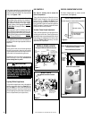
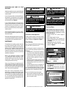
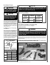
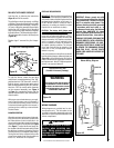
Air Hood
Remove 2 Screws
Figure 7
EDVI30
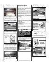
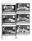
9. ENSURE THAT GAS SUPPLY IS SHUT OFF.
Disconnect gas line fitting at the valve (for
models EDVI30 & EDVI35). See
Figure 8.
Disconnect Gas
Line Fitting
Figure 8
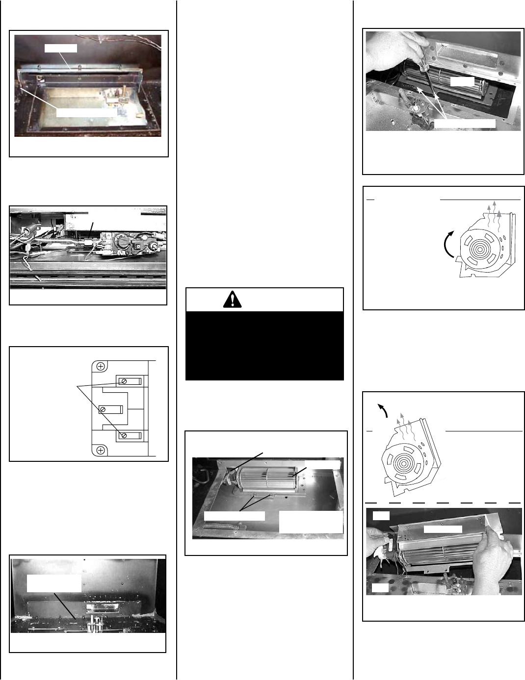
10. Disconnect the two burner circuit wires
from the valve terminals (see
Figure 9).
Disconnect Blue
Wires From Valve
Terminals
Figure 9
TH
TP
TP
TH
8. (EDVI30 only) Remove the two screws
shown in
Figure 7, then lift out air hood.
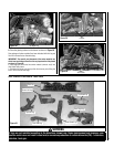
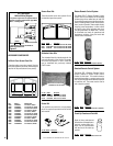
11. (EDVI30 only) Remove the screws around
the perimeter of the gas valve train, then
lift out and set aside (see
Figure 11).
12. (EDVI35 only) Remove the screws around
the perimeter of the blower access panel,
then lift out and set aside (see
Figure 10).
Remove Blower
Access Panel
Figure 10
EDVI35
Figure 11
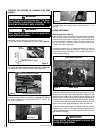
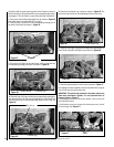
14. (EDVI35 only) Remove the blower per
instruction in
Figures 12 through 14.
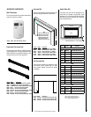
EDVI30
14. (EDVI35 ONLY) When reinstalling the
blower (reverse steps in
Figures 12
through 14),
15. To reinstall blower, reverse steps 1-14.
Remove 2 Screws
To remove, tip blower
back, pull it forward,
then tip back upright.
Disconnect wires from terminals & green
ground wire after blower is pulled forward.
Blower
13. (EDVI30 only) Remove the two blower
mounting screws and remove blower per
instructions in
Figure 11.
Remove 2 Screws
Blower
Figure 12 - EDVI35
Blower - RH Side View
Outlet
Rotate blower 45° clock-
wise toward the back,
then pull it forward so that
it is directly below the
blower access opening.
Rotate it so that the outlet
is again pointing upward.
Proceed to instructions in
Figure 14.
Access Opening
Figure 13 - EDVI35
Front
Back
Disconnect wires from terminals on blower (including green
ground wire). Proceed to instructions in Figure 13.
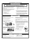
Rotate Blower 90°
counterclockwise,
while lifting blower up
at the same time. Lift
out as shown below.
Front
Back
Figure 14 - EDVI35
Blower Outlet
Front
Back