


13
NOTE: DIAGRAMS & ILLUSTRATIONS ARE NOT TO SCALE
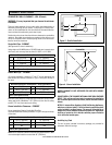
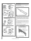
Combustible Wall Chimney Connector Pass-Throughs
Refer to Figure 9
Method A. 12” (305 mm) Clearance to Combustible Wall Member:
Using a minimum thickness 3.5” (89 mm) brick and a 5/8” (16 mm)
minimum wall thickness clay liner, construct a wall pass-through. The
clay liner must conform to ASTM C315 (Standard Specification for Clay
Fire Linings) or its equivalent. Keep a minimum of 12” (305 mm) of brick
masonry between the clay liner and wall combustibles. The clay liner
shall run from the brick masonry outer surface to the inner surface of
the chimney flue liner but not past the inner surface. Firmly grout or
cement the clay liner in place to the chimney flue liner.
Method B. 9” (229 mm) Clearance to Combustible Wall Member: Using
a 6” (153 mm) inside diameter, listed, factory-built Solid-Pak chimney
section with insulation of 1” (26 mm) or more, build a wall pass-through
with a minimum 9” (229 mm) air space between the outer wall of the
chimney length and wall combustibles. Use sheet metal supports
fastened securely to wall surfaces on all sides, to maintain the 9” (229
mm) air space. When fastening supports to chimney length, do not
penetrate the chimney liner (the inside wall of the Solid-Pak chimney).
The inner end of the Solid-Pak chimney section shall be flush with the
inside of the masonry chimney flue, and sealed with a non-water soluble
refractory cement. Use this cement to also seal to the brick masonry
penetration.
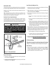
Method C. 6” (153 mm) Clearance to Combustible Wall Member:
Starting with a minimum 24 gage (.024” [.61 mm]) 6” (153 mm) metal
chimney connector, and a minimum 24 gage ventilated wall thimble which
has two air channels of 1” (26 mm) each, construct a wall pass-through.
There shall be a minimum 6” (153 mm) separation area containing
fiberglass insulation, from the outer surface of the wall thimble to wall
combustibles. Support the wall thimble, and cover its opening with a
24-gage minimum sheet metal support. Maintain the 6” (153 mm) space.
There should also be a support sized to fit and hold the metal chimney
connector. See that the supports are fastened securely to wall surfaces
on all sides. Make sure fasteners used to secure the metal chimney
connector do not penetrate chimney flue liner.
Method D. 2” (51 mm) Clearance to Combustible Wall Member: Start
with a solid-pak listed factory built chimney section at least 12” (304 mm)
long, with insulation of 1” (26 mm) or more, and an inside diameter of
8” (2 inches [51 mm] larger than the 6” [153 mm] chimney connector).
Use this as a pass-through for a minimum 24-gage single wall steel
chimney connector. Keep solid-pak section concentric with and spaced
1” (26 mm) off the chimney connector by way of sheet metal support
plates at both ends of chimney section. Cover opening with and sup-
port chimney section on both sides with 24 gage minimum sheet metal
supports. See that the supports are fastened securely to wall surfaces
on all sides. Make sure fasteners used to secure chimney section do
not penetrate chimney flue liner.
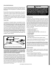
1. Connectors to a masonry chimney, excepting method B, shall extend
in one continuous section through the wall pass-through system and
the chimney wall, to but not past the inner flue liner face.
2. A chimney connector shall not pass through an attic or roof space,
closet or similar concealed space, or a floor, or ceiling.
3. Where passage through a wall, or partition of combustible construc-
tion is desired, the installation shall conform to CAN/CSA-B365.
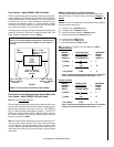
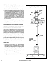
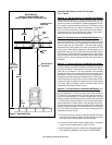
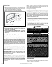
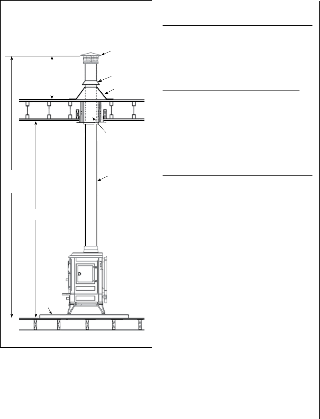
Termination Cap with
Spark Arrestor
Storm
Collar
Flashing
Support
Box
DVL Close Clearance
Connector Pipe
Floor
Protector
3 Feet
Minimum
7 Feet
Minimum
Minimum of
12-15’ of Flue to
achieve a stable
draft.
Double Wall Pipe
(Approved for Model CI2000HT Only)
Using 6” Diameter Type L-Vent Connector Pipe
Figure 8 - Double Wall Pipe