


12
NOTE: DIAGRAMS & ILLUSTRATIONS ARE NOT TO SCALE
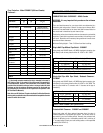
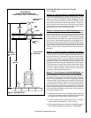
3) Drill a hole in the vent pipe per the draft gauge manufacturers instruc-
tions (to create a draft test port). Note: Hole location should be a
minimum of 1 foot above flue outlet collar.
4) Start a fire (See How To Start And Maintain A Fire on Page 15).
5) After the fire is well established (20-25 minutes) and burning at a low
setting, perform the draft test per the gauge manufacturer instructions.
The draft gauge should read between .05 and .06” W.C. (inches water
column). Excessive draft (above .06 W.C.I.) can result in too much
combustion air to be pulled into the firebox, this will produce hotter
burns and could result in overfiring. Too little draft (below .05” W.C.)
will not allow enough combustion air delivery to maintain a fire well
or cause performance problems such as smoking (this may result in
improper operation of appliance, i.e. will not maintain fire well unless
fuel door is left open).
6) Install a screw to seal the draft test port in the vent pipe. If the draft
test reading was not within the required range, correct the installation
and repeat this procedure.
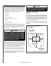
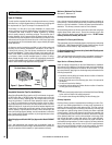
Ventilation Requirements / Provide Adequate Air For Combustion
THE FRESH AIR REQUIREMENTS OF THIS APPLIANCE MUST BE MET
WITHIN THE SPACE WHERE IT WILL BE INSTALLED. VENTILATION IS
ESSENTIAL WHEN USING A SOLID FUEL BURNING HEATER.
In well insulated and weather tight homes, it may be difficult to establish
a good draft up the chimney (caused by a shortage of air in the home).
The lack of air is caused by many common household appliances which
exhaust air from the home (such as a furnace, heat pump, air conditioner,
clothes dryer, exhaust fans, fireplaces, and other fuel burning appliances).
Also, the combustion process of this heater uses oxygen from inside the
dwelling. If the available fresh air delivery in the dwelling is insufficient
to support the demands of these appliances, problems can result (i.e.
excessive negative pressure can develop in the dwelling which will affect
the rate at which this appliance can draft thus resulting in performance
problems; See Draft Requirements on Page 11). To correct this problem
it may help to open a window (preferably on the windward side of the
house) or install a vent to provide make-up air into the dwelling.
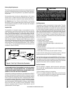
Important Notes:
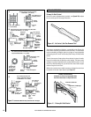
• Minimize the use of elbows (30°, 45° or 90°) - Offsets in the venting
system are very restrictive and will inhibit the draft (i.e. You will lose
approximately 5 feet of effective draft for every 90 degrees of direction
change). This appliance requires 12 to 15 feet of effective draft for
optimum performance (see Draft Requirements on Page 11).
• First section of pipe must be vertical - Use as much straight vertical
pipe directly above the appliance as possible before using an elbow
(a 2’ to 3’ initial vertical rise is suggested).
• See pipe manufacturers instructions for installation requirements of
venting components and vent clearances.
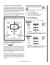
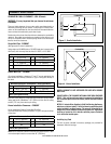
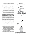
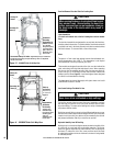
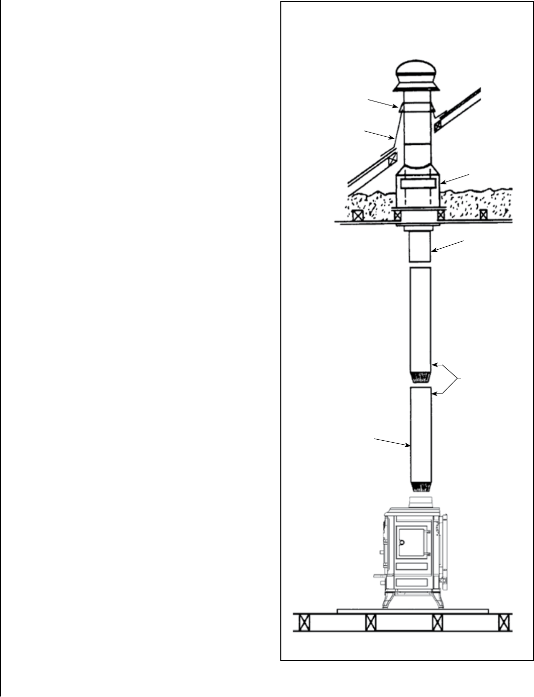
Chimney
Termination
Cap
Storm
Collar
Roof
Flashing
Ceiling Support
Assembly
Slip
Adapter
Chimney
Connector
6” x 24” 24-gage
black steel or 26 gage
blued steel single
wall pipe
Single Wall Pipe
Using 6” Diameter Single Wall Connector Pipe
Figure 7 - Single Wall Pipe