


11
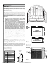
Install the two 3” (76 mm) long bolts (with the head up) through the
nuts attached to the insert on the lower rear corner of each side. This will
allow you to level the insert when placed into the fireplace. Measure from
the front of the top surround mount to the center of the flue. Determine
if there is an alignment problem in connecting a liner from the chimney
to the insert’s flue. If there is an alignment problem, connection can be
made using a short piece of stainless flex or a stainless steel offset box
(available from your dealer). Before installing the liner, make any attach-
ment brackets or drill any holes in the liner, offset box, or insert. Once
installed, it may be difficult or impossible to drill additional holes.
If additional support is necessary, factory punched holes in the front
corners of the bottom air chamber will accept leveling legs. Carefully
measure the distance from the hearth protection to the bottom of the
stove. Use 3/8” diameter bolts that are 1/2” (13 mm) longer that the
distance just measured. Thread a nut onto the the bolt approximately 1”
(25 mm). Lift the stove slightly and insert a bolt into each hole and then
thread the nut up the bolt until the front is securely supported. Install
another nut onto the bolt through the air space in the stove and tighten
securely. If desired an insert front support, Cat. No. H5296, is available
to fill the space between the insert and the hearth protection.
Install the brick and baffle as per Page 6.
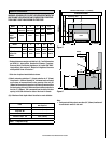
INSERT PRE-INSTALLATION PREPARATION
Place the insert into the fireplace, making sure to center it side to side.
Slide the insert in until the surround mounts are approximately 1/2” (13
mm) from the face of the fireplace where the surround panels cover.
Lower the chimney and make attachment to the insert. Level the stove
by using a 3/4” socket and a long extension and adjusting the bolts on
either side of the insert.
Install the side surround panels with the screws supplied. Push the insert
in until there is approximately a 1/4” (6 mm) gap between the back of the
surround panels and the face of the fireplace. Before installing the top
surround panel, make sure all connections are tight and that no part of
the insert or chimney is touching the firebox or chimney in the fireplace.
There must be a minimum of 1” (25 mm) clearance between the stove
and the zero clearance fireplace. Install the top surround panel.
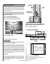
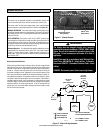
Remove the existing chimney cap and install a stainless steel liner into
the chimney (if a special section has been used or drilled to attach to the
insert, it must be the bottom piece). The next piece should be a dripless
slip joint; followed by the rest of the chimney liner. Fasten the chimney
at the top when it is positioned so that the slip joint will allow the lowest
piece to slide up enough to clear the insert during installation. Insulate
the top four to six feet between the liner and the chimney to prevent heat
loss. Install the cap and flash if necessary to prevent water or creosote
from entering the chimney’s venting system.
From inside the fireplace firebox, attach any adapters or flue offsets and
slide the liner up as far as necessary for the bottom piece to clear the
insert during installation.
INSTALLING THE INSERT
CHIMNEY LINER INSTALLATION
1. Check that all chimney pipe joints are securely fastened.
2. Check that the heater is securely fastened to the floor (if ap
-
plicable).
3. Make sure the intake vent has clear access to outside air (if ap
-
plicable).
4. Make sure the outside air vent has been sealed properly to keep
rodents out (if applicable).
5. Be sure all roof flashings are watertight (if applicable).
6. Be sure the stove is properly grounded (if applicable).
FOR YOUR OWN PROTECTION AND INSURANCE PURPOSES,
HAVE YOUR CHIMNEY AND CONNECTOR PIPE INSTALLATION
INSPECTED BY YOUR LOCAL BUILDING CODE AUTHORITY OR
FIRE MARSHAL BEFORE STARTING A FIRE IN YOUR STOVE.
NOTIFY YOUR INSURANCE COMPANY.
POST INSTALLATION CHECKS