


9
NOTE: DIAGRAMS & ILLUSTRATIONS NOT TO SCALE.
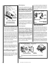
Figure 9
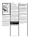
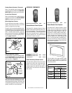
Electronic Appliance Checkout
To light the burner, refer to the lighting instruc-
tions on
page 13 and 14
. Ensure the ignitor lights
the pilot. The pilot flame should engulf the flame
sensor as shown in
Figure 10
.
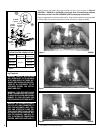
Figure 10
With proper care and maintenance, your appli-
ance will provide many years of enjoyment. If you
should experience any problem, first refer to the
trouble shooting guide in this manual. If problem
persists, contact your Lennox distributor.
Glowing Embers (Rockwool) Placement
Refer to the detailed glowing embers place-
ment instructions provided in the LOG PLACE-
MENT GUIDE accompanying this document.
Ceramic Panel Placement
Refer to the detailed ceramic panel placement
instructions provided in the LOG PLACEMENT
GUIDE accompanying this document.
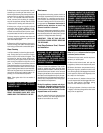
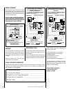
Millivolt Appliance Checkout
The pilot flame should be steady, not lifting or
floating. Flame should be blue in color with
traces of orange at the outer edge.
The top ³⁄₈" (10 mm) at the pilot generator (ther-
mopile) and the top ¹⁄₈" min (tip) of the quick drop
out thermocouple should be engulfed in the pilot
flame. The flame should project 1" (25 mm)
beyond the hood at all three ports. See
Figure 9.
To light the burner, refer to the lighting instruc-
tions on
pages 11 and 12.
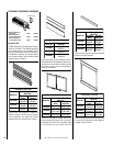
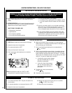
ACCESSORY COMPONENTS
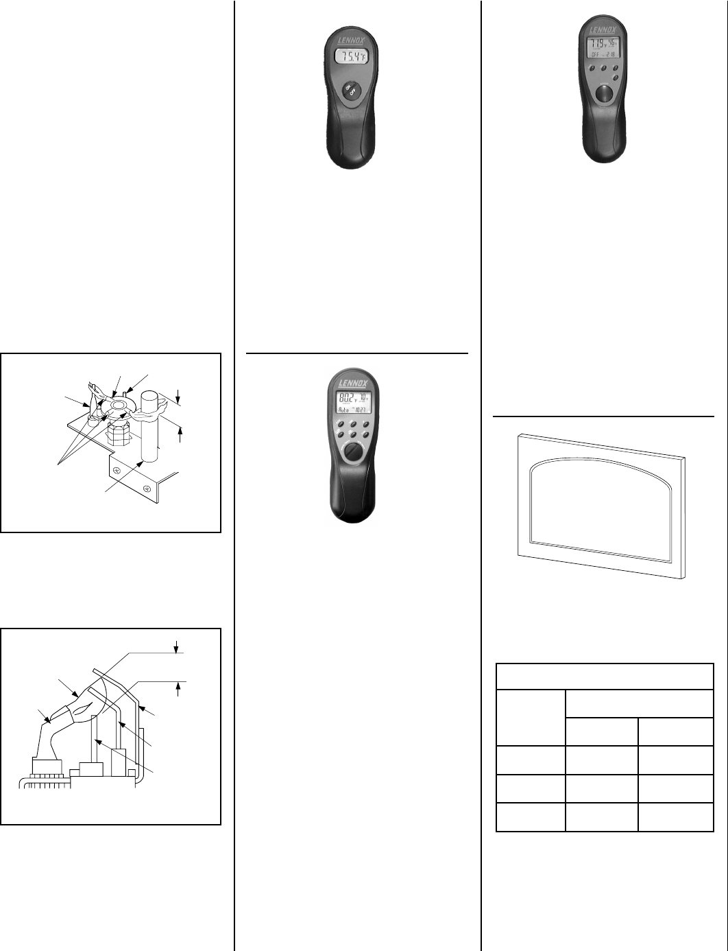
Remote Control System (Standard) H0249 RCL
Standard Remote Control System
The Model RCL (Standard) Remote Control
System, features a simple On/Off control func-
tion for the fireplace. This model includes a
hand-held transmitter, a remote receiver with
wall-mount coverplate and all hardware re-
quired to install the unit. The remote receiver
can be wall or hearth mounted.
Deluxe Remote Control System
The Model RCL-T (Deluxe) Remote Control
System has all of the features of the standard
system along with an added easy to read LCD
screen which presents access to many en-
hancements, including; battery power level in-
dicator, timer, mode of operation, thermostatic
display including room temperature in either
metric of English units, flame indicator and
clock. Fully programmable, the Model RCL-T
allows for command over nearly all operational
and temperature variables, using the hand held
remote control transmitter.
Remote Control System (Deluxe) H0251 RCL-T
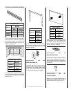
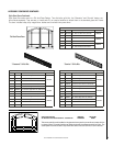
The kits attach to the glass enclosure panel
without the use of hardware. The decorative
arch kits can not be used in conjunction with
the screen panel kit.
MILLIVOLT
Thermocouple
Hood
Ignitor Rod
³⁄₈" Min
(9 mm)
Thermopile
Pilot
Nozzels
ELECTRONIC
Proper Flame
Adjustment
Pilot
Nozzle
3/8 To 1/2 Inch
(9 mm to 13 mm)
Ground
Electrode
Flame Rod
Hot Surface
Igniter
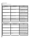
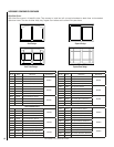
stiKrooDhcrA
.oNledoM
.oNgolataC
.oNledoM
dehsiloP
ssarB
dehsurB
sselniatS
0353VDE
43L18
BPC53KDA
86L89
SBC53KDA
5304VDE
53L18
BPC04KDA
96L89
SBC04KDA
0454VDE
63L18
BPC54KDA
07L89
SBC54KDA
Flame Modulating Remote Control
Flame Modulating Remote Controls were de-
veloped to provide a safe, reliable and user-
friendly remote control system for appli-
ances equipped with a Millivolt Gas Valve. A
detailed set of instructions are included with
each remote.
Flame Modulating Remote Control
– Natural Gas H0301 RCL-MN
Flame Modulating Remote Control
– LP/Propane Gas H0302 RCL-ML