


7
NOTE: DIAGRAMS & ILLUSTRATIONS ARE NOT TO SCALE.
Orifice Sizes - Sea Level to High Altitude
(All Models): These appliances are tested and
approved for installations at elevations of 0-4500
feet (0-1372 meters) above sea level using the
standard burner orifice sizes (marked with an
"*" in Table 4).
For higher elevations, contact your gas supplier
or qualified service technician.
Install the appliance according to the regulations
of the local authorities having jurisdiction and,
in the USA, the National Fuel Gas Code NFPA
54 / ANSI Z223.1 - latest edition or, in Canada,
the CAN/CSA-B149.1- latest edition.
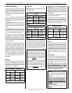
Burner Orifice Sizes
Elevation 0-4500 feet ( 0-1372 meters)
Model Nat.Gas
drill size (inches)
Propane
drill size (inches)
LSM40-2 0.1405" (#28)*
•H2286
0.086" (#44)*
•H2287
LSM45-2 0.161" (#20)*
•H2288
0.093" (#42)*
•H4816
Table 4
* Standard size installed at factory
•Part/Cat.Number
Deration
At higher elevations, the amount of BTU fuel
value delivered must be reduced by either using
gas that has been derated by the gas company
or by changing the burner orifice to a smaller
size as regulated by the local authorities having
jurisdiction and by the (USA) National Fuel Gas
Code NFPA 54/ANSI Z223.1 - latest edition or,
in Canada, the CAN/CSA-B149.1 codes - latest
edition.
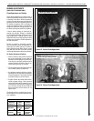
Burn-in Period
During the first few fires of this appliance there
will be some odor due to the curing of the
paint and burning off of lubricants used in the
manufacturing process. Depending on your
use, the burn-in period may take a few hours
or a few days.
KEEP YOUR HOUSE WELL VENTILATED
DURING THE CURING PROCESS. THE ODOR
AND HAZE EMITTED DURING THE CURING
PROCESS CAN BE QUITE NOTICEABLE AND
MAY SET OFF A SMOKE DETECTOR.
Input (BTU/HR) - All Models
Natural Gas Propane Gas
Model
No.
Input
(BTU/Hr)
Model
No.
Input
(BTU/Hr)
LSM40-2
40,000 to
50,000
LSM40-2
40,000 to
50,000
LSM45-2
47,000 to
60,000
LSM45-2
48,000 to
60,000
Table 1
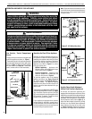
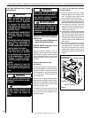
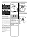
Test gauge connections are provided on the
front of the millivolt and electronic gas control
valve, identified IN for the inlet and OUT for the
manifold side (see Figures 2 and 3 on Page 8).
The control valves have a 3/8" (10 mm) NPT
thread inlet and outlet side of the valve.
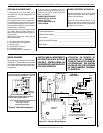
GENERAL INFORMATION
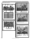
The fireplace models covered in this manual are
direct-vent, sealed combustion gas fireplaces
designed for residential application. Direct-
vent appliances operate with the combustion
chamber completely isolated from the indoor
environment.
All air for combustion is brought in from the
outside and exhaust gases are vented through
the same direct-vent, co-axial (intake/exhaust)
vent system.
The Millivolt appliances are designed to oper-
ate on either natural or propane gas and have
a millivolt gas control valve with piezo ignition
system.
The Electronic appliances are designed to oper-
ate on natural gas only and contain an electronic
intermittent pilot system. External electrical
power is required to operate these units.
These appliances comply with National Safety
Standards and are tested and listed by OMNI-
Test Laboratories, Inc. (Report No. 116-F-22-5)
to ANSI Z21.50 (in Canada, CSA-2.22), and CAN/
CGA-2.17-M91 in both the USA and Canada as
vented gas fireplaces.
The Installation must conform to local codes or,
in the absence of local codes, with the National
Fuel Gas Code, ANSI Z223.1/NFPA 54 - latest
edition, or the Natural Gas and Propane Instal-
lation Code, CSA B149.1 - latest edition. The
appliance, when installed, must be electrically
grounded in accordance with local codes or, in
the absence of local codes, with the National
Electrical Code, ANSI/NFPA 70 - latest edition,
or the Canadian Electrical Code, CSA C22.1 -
latest edition.
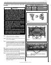
NOTICE: A white film may develop
on the glass enclosure panel during
the first few fires as part of the burn-in
process.
The first few times you use the
fireplace, clean the glass after each use
(AFTER THE GLASS HAS COMPLETELY
COOLED); otherwise, the white film
will bake onto the glass and become
difficult to remove.
See glass cleaning instructions on
Page 9.
LENNOX HEARTH PRODUCTS • MONTEBELLO
®
DV GAS FIREPLACES (LSM40/45MN-2, LSM40/45MP-2, LSM40/45EN-2) • CARE AND OPERATION INSTRUCTIONS
BTU Input
Millivolt and electronic models come standard
with a manually-modulated gas valve; flame
appearance and heat output can be controlled
at the gas valve. The BTU Input for these ap-
pliances are shown in Table 1.
Gas Pressure
Tables 2 and 3 show the appliances' gas pres-
sure requirements.
Inlet Gas Supply Pressure
(all models)
Fuel # Minimum Maximum
Natural Gas
5.5" WC
(1.37 kPa)
10.5" WC
(2.61 kPa)
Propane
11.0" WC
(2.74 kPa)
13.0" WC
(3.23 kPa)
Table 2
Manifold Gas Supply Pressure
(all models)
Fuel # Low High
Natural
Gas
(Lo) 2.2" WC
(0.55 kPa)
(Hi) 3.5" WC
(0.87 kPa)
Propane
(Lo) 6.3" WC
(1.57 kPa)
(Hi) 10.0" WC
(2.49 kPa)
Table 3
These appliances must be isolated from
the gas supply piping system (by closing
their individual manual shut-off valve)
during any pressure testing of the gas
supply piping system at test pressures
equal to or less than 1/2 psig (3.5 kPa).
These appliances and their individual
shut-off valves must be disconnected
from the gas supply piping system dur-
ing any pressure testing of that system
at pressures greater than 1/2 psig (3.5
kPa).