


14
NOTE: DIAGRAMS & ILLUSTRATIONS ARE NOT TO SCALE.
LENNOX HEARTH PRODUCTS • MONTEBELLO
®
DV GAS FIREPLACES (LSM40/45MN-2, LSM40/45MP-2, LSM40/45EN-2) • CARE AND OPERATION INSTRUCTIONS
The following paragraphs address burner
adjustment concerns and procedures.
When lit for the first time, this appliance will emit
a slight odor for an hour or two. This is due to
the “burn-in” of internal paints and lubricants
used in the manufacturing process.
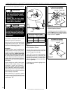
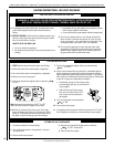
Adjustment
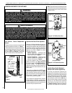
To adjust the flame, move the adjustment air
shutter (located on the lower venturi) back or
forward to increase or reduce the air shutter
opening, respectively. Position the air shut-
ter to the factory setting as shown in Figure
15. Allow the burner to operate for at least 15
minutes. Observe the flame continuously. If it
appears weak or sooty as previously described,
adjust the air shutter until the flame appearance
is as desired.
Propane models may exhibit a flame pattern
that may candle or appear stringy. If this is
problematic or persists as the appliance is
continually operated, adjust the air shutter
open as described in the previous paragraphs.
Operate the appliance for a period of time as the
effect diminishes, ensuring that the appliance
does not develop sooty flames.
When satisfied that the appliance operates
properly, proceed to finish the installation. Leave
the control knob in “ON” position and turn the
remote switch “OFF.”
WARNING
• Air shutter adjustment should
only be performed by a quali-
fied professional service
technician.
• Ensure that the front glass
door assembly is in place and
sealed After adjustment.
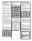
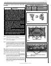
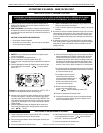
Figure 15
Main Burner Factory Air Shutter
Opening Setting - Inches (millimeter)
Model Nat.Gas Propane Gas
LSM40-2
1/16 (1.59) 9/32 (7.14)
LSM45-2
1/16 (1.59) 9/32 (7.14)
CAUTION
Soot will be produced if the air
shutter is closed too much. Any
damage due to carboning result-
ing from improperly setting the
air shutter is not covered under
the warranty.
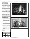
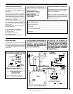
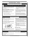
Electronic Appliance Checkout
To light the burner, refer to the lighting instruc-
tions on Page 20. Ensure the igniter lights the
pilot. The pilot flame should engulf the flame
sensor as shown in Figure 17.
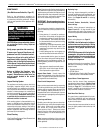
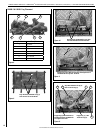
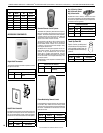
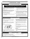
Millivolt Appliance Checkout
The pilot flame should be steady, not lifting
or floating. Flame should be blue in color with
traces of orange at the outer edge.
The top 3/8" (10 mm) at the pilot generator
(thermopile) and the top 1/8" minimum (tip)
of the quick drop out thermocouple should be
engulfed in the pilot flame. The flame should
project 1" (25 mm) beyond the hood at all three
ports (see Figure 16).
To light the burner, refer to the lighting instruc-
tions on Page 18.
Figure 17
Pilot
Nozzels
ELECTRONIC PILOT ASSEMBLY
Proper Pilot Flame Appearance
Flame
Sensor
Pilot Hood
Igniter
Rod
Figure 16
Thermocouple
Thermopile
Pilot
Nozzels
SIT MILLIVOLT PILOT ASSEMBLY
Igniter Rod
Pilot Hood
Proper Pilot Flame Appearance
3/8" Min.
(9 mm)
Air Shutter
Opening
Venturi
Orifice
Gas Valve
Burner
Venturi
Burner Air Shutter Adjustment Procedure