


FIREPLACE INSTALLATION
Locating The Montecito Estate™
The best location to install your fireplace is determined by considering
the location of windows, doors, and the traffic flow in the room where
the fireplace is located, allowing space in front of the unit for the hearth
extension and the mantel, and taking into consideration the location of
the hot air ducts (optional), outside air kit and chimney. If possible,
you should choose a location where the chimney will pass through the
house without cutting floor or roof joists (see fireplace dimensions on
Pages 8 & 9
).
Usually, no additional floor support is needed for the fireplace. The ad-
equacy of the floor can be checked by first estimating the weight of the
fireplace system. Weights are given in the appendix. Next, measure the
area occupied by the fireplace. Note the floor construction and consult
your local building code to determine if additional support is needed.
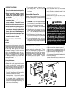
The Montecito Estate may be installed directly on the floor or on a raised
base and a minimum of 80” measured from the base of the appliance to
the ceiling is required.
Facade Installation
Install the Facade per instructions provided in Facade Kit (ordered sepa-
rately - see Page 20).
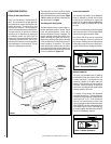
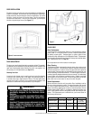
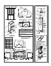
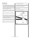
Hearth Extension Requirements
The Montecito Estate may be installed directly on a combustible floor;
however, the combustible floor in front of the fireplace must be covered
with one inch (1 in) of non-combustible support material (cement board,
cement block or other) before applying the finish material (tile, marble,
stone, etc). See Figure 8.
Figure 8
Hearth Extension Requirements
56” Min.
Non-Combustible Material
46-5/16”
16”
24”
24”
Fireplace
Minimum 1”
Cement Board
Tile or Marble
2” x 4” Framing
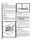
Figure 9
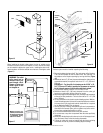
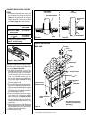
Framing, Facing And Mantel
The construction of the framing, facing, and mantel must be in accordance
with the standards and the following illustrations (Figures 10 & 11):
A. Frame the fireplace using 2” x 3” or heavier lumber.
B. WARNING: Combustible materials cannot be used in the space
directly above the fireplace, except for the studs above the fa-
cade that support the facing and mantel. This area must remain
empty for a height of 80” (2,032 mm) measured from the base
of the appliance.
C. Frame the fireplace with vertical studs at the sides of the fireplace run-
ning from floor to ceiling (see Figure 10). If combustible facing is to
be used, position the studs back, from the front edge of the fireplace
(a space that is the thickness of the facing material, so that the fac-
ing can be installed flush with the fireplace facing). Frame headers
between the vertical studs only as follows:
- Place 2” x 3” or 2” x 4” headers, only along the upper part of the
front, side and back faces (some codes may require a 2” x 6” on
an outside bearing wall). Do not put wood or any combustible
material within the area above the fireplace except on the front
facing.
- Place headers only as required to support the facing and man
-
tel.
D. WARNING: The fireplace must not be in contact with any insula-
tion or loose filling material. Cover the insulation with Drywall
panels around the fireplace.
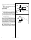
COLD CLIMATE INSTALLATIONS
Climates where temperatures will fall below 32° F (0° C).
The heating performance of the appliance will vary depending upon the
level of insulation, house design, how the appliance is operated, etc.
If this fireplace is being installed in a cold climate, it is especially important
to seal all cracks around the fireplace and wherever cold air could enter
the room with noncombustible material. Also, the outside air inlet duct
should be wrapped with noncombustible insulation to minimize the
formation of condensation. Do not place insulation materials directly
against the chimney sections. We recommend that you use the insulated
wall radiation shield since it will maintain the home’s thermal barrier. AC
chimney is NOT recommended in cold climates.
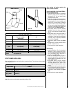
Hearth
45 Deg.
Area where
wood Mantel
can be
installed
4”
NOTE: DIAGRAMS & ILLUSTRATIONS ARE NOT TO SCALE.
8