


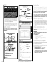
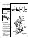

1. Combustible material must be installed flush
with the fireplace. It may not project in front
of and on the fireplace (i.e. the steel facade
of the fireplace) (Figure 14).
2. Non-combustible materials such as brick,
stone or ceramic tile may project in front of
and onto the fireplace facing (Figure 13).
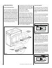
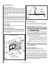
MANTEL & FACING
The mantel must be installed at least 56”
(1143 mm) above the base of the fireplace
(Figure 13).
Figure 13
IMPORTANT
The facade must be removable
once installed. The facade is
designed to overlap any facing
material installed on the front of
the fireplace. If thicker material
is installed, use the facade as a
template and make sure it can be
easily removed for servicing.
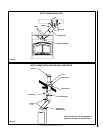
FACING
1
3
4
5
6
2
1
2
7
3
4
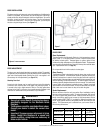
1. Fireplace
2. Front of fireplace
3. Wood frame (2” x 3” min)
4. Drywall
5. Tiles
6. Rock board or other
7. Brick
Fireplace Frame Section
(Top View)
Figure 12
...
..
...
..
...
..
...
..
...
..
...
..
...
..
...
..
...
..
...
..
...
..
...
..
...
..
...
..
...
..
...
..
...
..
...
..
...
..
...
..
...
..
...
..
...
..
...
..
...
..
...
..
...
..
...
..
...
..
...
..
...
..
...
..
...
..
...
..
...
..
...
..
...
..
...
..
...
..
...
..
...
..
...
..
...
..
...
..
...
..
...
..
...
..
...
..
...
..
...
..
...
..
...
..
...
..
...
..
...
..
...
..
...
..
...
..
...
..
...
..
...
..
...
..
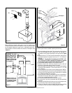
Mantel
Rock Board
or Other
Noncombustible
Facing
56”
Drywall
2” X 3” Min.
Spacer
Mantel & Facing
(Side View)
Figure 15
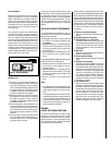
Drywall
2” X 3” Min.
Spacer
Noncombustible Facing
Only non-combustible material
should be superposed or project-
ing over the front of the fireplace.
Figure 14
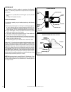
50”
Min.
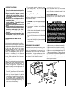
Fireplace Blower
The fireplace comes equipped with a heat acti-
vated blower. It is located in the bottom of the
fireplace, towards the back. It uses 120 V and
must be connected to the main electrical circuit
by a qualified electrician. For connection, use the
electrical box supplied with the unit located on
the bottom right corner of the fireplace.
If you wish to adjust the blower speed, the
variable speed control (VRUW) provided must
be installed in line with the wiring. Again, use
a qualified electrician for installation.
If the blower requires servicing,
1- Remove the doors and decorative facade.
2- Remove the screw located below the blower
motor that holds it to the back of fireplace.
3- Pull the blower out of the unit through the
square hole located in the front bottom right
corner.
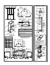
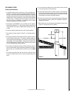
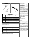
HOT AIR DUCTING INSTALLATION
The Montecito Estate™ is approved for use with
a Gravity Kit:
Gravity Kit
The gravity kit is designed for double hot air
outlets and includes:
(See Figure 16)
- 2 telescopic lengths 8” I.D.
- 2 90º elbows 8” I.D.
- 2 hot air outlet kits (grill and frames)
- 2 adaptors
See Gravity Kit Accessories on Page 20.
Only the blower available with the fireplace can
be used with the gravity kit.
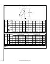
For safe installation, the gravity kit must meet
the following requirements:
Minimum height* 68” (1,727 mm)
Maximum length See Figure 17
* The height of the louver must be measured
from the base of the Montecito Estate to the
middle point of the louver.
NOTE: DIAGRAMS & ILLUSTRATIONS ARE NOT TO SCALE.
10