


MODEL 2535
Rev. C 9/04
3
2515ES
Rev. C 9/04
6
2515ES
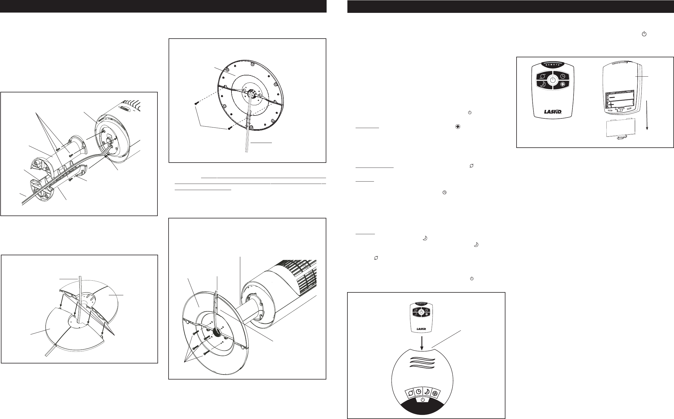
REMOTE CONTROL
(Figure 6)
1. Install the two “AAA” batteries supplied as shown in
Figure 6
.
2. The Remote Control Power Button is labeled as (
).
3. All the functions performed with the Remote Control work
identically to the Manual Controls.
MAINTENANCE
WARNING: ALWAYS UNPLUG THE CORD BEFORE MOVING
OR SERVICING.
WARNING: DO NOT IMMERSE FAN IN WATER!
CLEANING: Clean the Fan with the vacuum brush attachment
on your vacuum cleaner. This will remove dirt and lint that may
accumulate over time. DO NOT ATTEMPT TO TAKE APART
FAN. Clean the body of the Fan with a soft cloth.
CAUTION: Do not use gasoline, benzine, thinner, harsh clean-
ers, etc. as they may damage the Fan. NEVER use ALCOHOL
OR SOLVENTS.
SERVICING: All other servicing, with the exception of general user
maintenance, should be performed by an authorized service repre-
sentative. Call 1-800-233-0268, Monday through Friday, between
the hours of 8:00 a.m. and 5:00 p.m. EST for the location of your
nearest service center.
STORAGE: Store the Fan, with these instructions, in a cool, dry place.
MODEL 2515
MODELO 2515
Figure 5
Front of
Remote
Back of
Remote
Figure 6
ARMADO
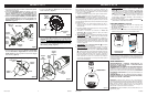
1. Para facilitar el armado, recueste el Ventilador de modo que la
parrilla negra y el tablero de control den hacia arriba.
2. Localice el
Cable Eléctrico
en la parte inferior del Ventilador.
Coloque el
Cable Eléctrico
en los
Canales Para Cable
de los
Soportes De Columna
. Encaje firmemente los
Soportes De
Columna
el uno con el otro de modo de formar un
Conjunto De
Soportes De Columna
.
(Figura 1)
3. Una el
Conjunto De Soportes De Columna
a la
Base Del Motor
con
(4) Tornillos M5 de 1/2”de largo
. Cerciórese de alinear la
Llave
del
Conjunto De Soportes De Columna
con la
Muesca
Localizadora
de la
Base Del Motor
.
(Figura 1)
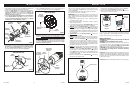
4. Arme las Bases de Soporte, introduciendo las
Copas
en la
Base
de Soporte A
en los
Orificios De Copas
de la
Base de Soporte
B
. Pase el
Cable de Electricidad
por el orificio grande en el
centro del Conjunto de la Base de Soporte.
(Figura 2)
5. Fije los
Tornillos (2) #8 X 1/2”
en los cuatro orificios que se
encuentran en la parte inferior de la base.
(Figura 3)
6. Alinee el
Conjunto de la Base de Soporte
con el
Soporte de
Columna
, cerciorándose de que el canal del cable en la parte
inferior de la base de soporte esté orientado hacia la parte
posterior del Ventilador. Ensamble el
Conjunto de la Base de
Soporte
con el
Conjunto del Soporte de Columna
utilizando
los
Tornillos M5 de (4) 1”
de largo. Jale con cuidado toda holgura
excesiva del
Cable de Electricidad
e introdúzcala por el
Canal
Conductor de Cable
.
(Figura 4)
Cable
Eléctrico
Canales
Para Cable
Soportes
De Columna
Base Del
Motor
Muesca
Localizadora
Tornillos
M5 de 1/2”
Conjunto De Soportes De Columna
Llave
Soportes
De Columna
Figura 1
Cable
Eléctrico
Base de
Soporte B
Base de
Soporte A
Copas
Conjunto de la Base de Soporte -
Vista des de Arriba
Figura 2
Conjunto de la Base de Soporte -
Vista des de Abajo
Conjunto
de la Base
de Soporte
#8 X 1/2”
Tornillos
Cable
Eléctrico
Figura 3
M5 X 1”
Tornillos
Conjunto De
Soportes De
Columna
Cable
Eléctrico
Canal
Conductor
de Cable
Conjunto
de la Base
de Soporte
Figura 4
Remote Storage
OPERATION
This Fan may be operated by the Manual Controls located on top
of the unit (as shown in
Figure 5
) or by the Remote Control
(shown in
Figure 6)
.
1. Remove the Fan from the carton and assemble as instructed.
2. Place the Fan on a firm, level surface.
WARNING: Plastic or rubber tabs, like the feet on this unit, may
stick to hardwood floors. The unit may leave a residue that could
darken, stain or leave permanent blemishes on the finish of certain
hardwood floors.
3. Plug the power supply cord into a 120 V~ electrical outlet. Be
sure plug fits tightly in outlet.
4. When the Fan is plugged in, there will be a “beep” to indicate
there is power to the unit.
5. Turn the Fan ON by pressing the
Power Button
( ). The Fan will
“beep” twice to indicate that the unit has been turned ON.
6.
SPEEDS: Press the
Fan Speed Button
( ) to desired speed
setting. Each time the Fan Speed Button is pressed, the speed
will change from Low (1), to Medium (2), to High (3). When intially
plugged in, the Fan will be in Low Speed. When the Fan is turned
OFF and ON again, the unit will resume the speed at which it
was turned OFF.
7.
OSCILLATION: Press the
Oscillation Button
( ) to start and
stop the oscillation function.
8. TIMER: The timer function allows the unit to be set to operate
for a length of time from 1/2 hour to 7 1/2 hours, in increments of
a 1/2 hour. Press the
Timer Button
( ) to set the length of time
desired. Each time the timer button is pressed, the time is
increased by 1/2 hour. After reaching 7 1/2 hours, pressing the
timer button once more will reset the Fan to continuous running.
The lights on the front of the unit will light up appropriately with
the length of time that the Fan is set for.
9.
SLEEP: This function allows the unit to be set in Sleep Mode.
Pressing the
Sleep Button
( ) once will set the unit on Low for
6 continuous hours. Pressing the
Sleep Button
( ) a second
time will reset the unit to 6 continuous hours. The Oscillation
Button ( ) will function when the Fan is in Sleep Mode. Pressing
any other button (Timer, Fan Speed or the Power Button) will
shut off the Sleep Mode.
10.To turn the Fan OFF, press the
Power Button
( ) and unplug
the unit from the electrical outlet.
If you lose your remote control, please call Customer Service to
order a replacement at 1-800-233-0268, Monday through Friday,
between the hours of 8:00 a.m. and 5:00 p.m. EST.
Conjunto de Columna Para la Base