


Page 14
19562-1-0606
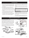
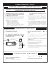
The appliance, when installed, must be electrically grounded in ac-
cordance with local codes or, in the absence of local codes, with the
National Electrical Code, ANSI/NFPA 70 or Canadian Electrical Code,
CSA C22.1, if an external electrical source is utilized.
This appli-
ance is equipped with a three-prong [grounding] plug for your
protection against shock hazard and should be plugged directly
into a properly grounded three-prong receptacle. Do not cut or
remove the grounding prong from this plug. For an ungrounded
receptacle, an adapter, which has two prongs and a wire for ground
-
ing, can be purchased, plugged into the ungrounded receptacle and
its wire connected to the receptacle mounting screw. With this wire
completing the ground, the appliance cord plug can be plugged into
the adapter and be electrically grounded.
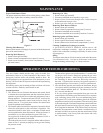
CAUTION: Label all wires prior to disconnection when servicing
controls. Wiring errors can cause improper and dangerous
operation. Verify proper operation after servicing.
Note: For testing flame sensor circuit use a micro-amp meter in
series with sensor. Minimum current should be 1 micro-amp dur
-
ing operation. Be careful as flame sensor is in the 115VAC circuit.
If current is below 1 micro-amp, remove sensor, clean with light
sandpaper and retest.
Note: This heater is equipped with a remote bulb electronic thermistor
control located down low at the back of the furnace. Sometimes due
to field locations different air currents may effect the control sensing
of the thermistor. This sensing bulb can be re-located if necessary to
provided for better room air sensing and control.
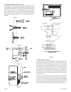
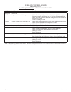
Replacement of Thermistor with 24 Volt Wall Thermostat
1. If furnace is installed, turn off gas supply and electric supply.
2. Remove casing front.
3. Remove black hose from front nipple on pressure switch.
4. Remove junction box cover (4 screws).
5. Please refer to wiring diagram for removal of the following
wires.
6. Internal Electronic Thermostat/Temperature Control
Board
Attention! No 24 volt wall thermostat wires are to be at
-
tached to the internal electronic thermostat.
7. Control Board
A. Remove white wire form screw marked W.
B. Remove yellow wire from screw marked C.
C. Remove red wire from screw marked R.
8. Route (2) wires from any 24 volt wall thermostat through the
casing back of furnace to the screws marked W and R on the
control board.
9. Replace junction box cover (4 screws).
10. Replace black hose onto front nipple on pressure switch.
11. Replacement of thermistor with 24 volt wall thermostat is
completed.
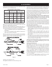
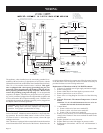
CIRCULATINGAIRBLOWER
WHT
FS
LS
RED
YEL
RED
BLK
1
PUR
PUR
INDUCER
BLOWER
BLU
BLU
6
5
3
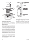
IFANYOF THEORIGINALWIREASSUPPLIEDWITHTHE
APPLIANCE MUSTBE REPLACED, ITMUST BEREPLACED
WITHAWIRE OFATLEAST105
°
CTEMPERATURERATING.
LIMITSWITCH
SECONDARY
FIELD INSTALLED
THERMOSTAT
24 VOLT
115 V
AC
SWITCH
LIMIT
3AFUSE
GND
BLACK
WHITE
ON/OFF
ROLLOUT
PRESSURE
SWITCH
R-8191
VALVE
GAS
TRANSFORMER
24 VAC
PRIMARY 115 VAC
COMMON
DISCONNECTINTEGRALTHERMOSTAT"R","W",AND "C"LEADSANDATTACHWALLTHERMOSTATASSHOWN
RW
5
6
PS
ROS
RED
GRN
ORG
7
8
9
ORG
ELECTRONIC
THERMOSTAT
INTEGRAL
WHT
YEL
RED
2
3
GR
Y
BRN
BRN
GV
GR
Y
24
V
WH
T
BLK
115 V
OPTIONALWALLMOUNTTHERMOSTAT
XFMR
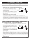
ON/OFF
BLACK NEUTRAL
RIBBED
INSULATION
BLACK HOT
SMOOTH
INSULATION
CIRCULATINGAIR
BLOWER MOTOR
RED LED
STATUS
LIGHT
IGN
HOTSURFACE
IGNITOR
POWER SWITCH
INDUCER MOTOR
FLAME SENSOR
COMBUSTIONAIR
ROS =ROLLOUT LIMITSWITCH
IGN =HOT SURFACE IGNITOR
PS =PRESSURESWITCH
XFMR =TRANSFORMER
CORDSET115VAC
FS =FLAMESENSOR
GV =GAS VALVE
LS =LIMITSWITCH
4
2
4
1
WIRING