


Page 12
19562-1-0606
Figure 11
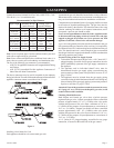
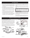
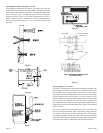
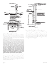
Condensate Removal (Figures 11 and 12)
The condensate drain kit is used in conjunction with DVE and
DVE-2, intake/exhaust extension kits. The condensate drain kit is
required whenever there is a vertical vent run, in a heated room [10
ft. (3m) or more for DV-40E or 6 ft. (1.8m) or more for DV-20E],
in the intake/exhaust venting.
Whenever a vertical vent run, in a heated room [10 ft. (3m) or more
for DV-40E or 6 ft. (1.8m) or more for DV-20E] and a horizontal
vent run are combined, you must purchase the optional condensate
drain kit, part number DV-1108. If the vertical vent run lengths are
less than those required for the condensate drain kit, you can slope
the horizontal vent run portion, downward 1/4" (6mm) per foot
(.3m) to the outside. However, if local codes prohibit condensate
from draining outside and the appliance produces condensate, the
horizontal portion of the vent run must slope downward, to the
appliance, 1/4" (6mm) per foot (.3m). This will allow any condensate
to flow into the condensate drain kit. Do not use the orange silicone
elbow supplied with unit to catch condensate. You can route the
condensate from the condensate drain kit to an existing drain or
into the condensate drain pan located within the appliance.
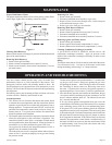
Whenever a horizontal vent run is used, where local codes allow,
you can slope the exhaust pipe downward, to the outside, 1/4"
(6mm) per foot (305mm). The downward slope on the exhaust
pipe will allow any condensate to flow out of the exhaust pipe. If
local codes prohibit condensate from draining to the outside and
the appliance produces condensate you must purchase condensate
drain kit, part number DV-1108.
INTAKE
SLOPE THE VENT TERMINAL
HORIZONTAL RUN DOWNWARD
THE OUTSIDE TO DRAIN OUT
ANY CONDENSATE
EXHAUST
VENT TERMINAL
EXHAUSTAIR
ELBOW WITHCLAMPS
INTAKEAIR
SUPPORTSTAP EVERY
5 FT. (1.5m)MIN.
SHROUD SIDE
EXHAUSTAIR
INTAKEAIR
EXTERIOR
W
ALL
COUPLING WITH
HOSE CLAMPS
SLOPE DOWNWARD1/4" (6mm)
PER FOOT(m)TO DRAINANY
CONDENSATE OUTSIDE
FILTER
TEMPERATURE CONTROLDOOR
INTERIOR WALL
Figure 12
Reassembly and Resealing Vent-Air Intake System
When vent-air intake system is removed for servicing the furnace,
the following steps will assure proper reassembly and resealing
of the vent-air intake assembly. Be sure all hose connections and
elbow assemblies are re-secured in place using the hose clamps
removed. Reattach all screws securing mounting flanges and inspect
all connections for a tight fit. Use high temperature silicone caulk
rated at 204°C/400°F to reseal the inlet air vent pipe and exhaust
air vent pipe to the mounting plate.