


Page 1112431-7-0107
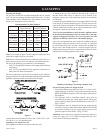
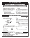
4. Apply furnace cement to 4" diameter flue outlet collar on
combustion chamber and to 4" diameter collar on vent cap.
Attach 4" diameter flue outlet tube onto flue outlet collar on
combustion chamber. Attach vent cap into the 4" diameter flue
outlet tube. Attach vent cap to outside mounting plate with (3)
#10 x 1/2" screws provided.
5. Reassembly and resealing vent-air intake system is completed.
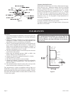
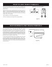
Installing a Vent Near a Window Ledge,
Other Type of Projection or on Siding (vinyl, aluminum, etc.)
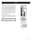
Direct vent furnaces are designed to be installed on a uniform
outside wall. When the wind comes from any angle (up, down or
from either side), it must hit the vent cap equally over both the air
inlet and the flue outlet portions of the vent. Any wall projection,
such as a door or window casing, which disturbs the wind on one
side of the air inlet section will result in back pressure on the flue
section smothering the flame and eventual pilot outage.
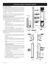
When the vent cap is to be installed on siding or it appears that a
projection within 6" of any side of the air inlet section could shield
the air inlet section, the entire vent should be supported away from
the wall at least the distance of the projection. 2" x 4" framing
whose outside dimensions match the overall dimensions of the
mounting plate is recommended. The 2" x 4" framing protects sid
-
ing from possible warpage or discoloration. All joints can then be
sealed and painted. The wall depth plus the additional depth of the
2" x 4" framing should not exceed a total depth of 13" for DV-55.
(See Figure 9)
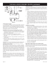
Vinyl siding vent kit, DV-822, is available from Empire Comfort
Systems, Inc. The depth is 3", which enables the vent cap to be
extended away from siding or projections. The wall depth plus the
additional 3" depth of the vinyl siding vent cap extension should
not exceed a total depth of 13" for DV-55. (See Figure10)
Warning: When vinyl siding vent kit, DV-822 or 2" x 4"
framing is added to an existing installation (furnace is
installed) do not attempt to add sections of pipe to the flue
outlet tube or air inlet tube. An air tight seal is required for
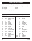
both tubes. Refer to Parts List, page 16 to order tubes.
Figure 9 Figure 10
INSTALLATION INSTRUCTIONS (continued)