


Page 10 12431-7-0107
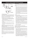
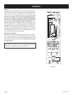
Cutting Vent Tubes
This is the most important part of the installation. With the furnace
installed on wall the 6" diameter air inlet tube and the 4" diam-
eter flue outlet tube are to be marked and cut using the following
procedure.
1. Attach 6" diameter air inlet tube onto the collar of air drop
assembly. Be sure 6" diameter air inlet tube is placed as far as
possible onto the collar of the air drop assembly. Mark the 6"
diameter air inlet tube 1/2" beyond the outside wall. Remove
6" diameter air inlet tube from collar of air drop assembly.
2. Attach 4" diameter flue outlet tube onto flue outlet collar on
combustion chamber. Be sure 4" diameter flue outlet tube is
placed as far as possible onto the collar of flue outlet. Mark
the 4" diameter flue outlet tube 2 1/4" beyond the outside wall.
Remove 4" diameter flue outlet tube from collar of flue outlet
on combustion chamber.
3. Mark or wrap tape completely around the tubes at the marked
points to help in making a true cut. Do not crimp or enlarge
tubes.
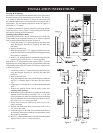
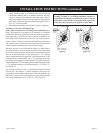
Installing Vent Assembly
1. Place provided caulking beneath the edge of the outside
mounting plate. Use additional caulking to correct uneven
wall surface, such as clapboard.
2. Attach 6" diameter air inlet tube onto the collar of air drop
assembly. Attach caulked, outside mounting plate into the 6"
diameter air inlet tube. Position the outside mounting plate so
that 6" diameter air inlet tube has a slight downward slope to
the outside. The downward slope is necessary to prevent the
entry of rainwater. Attach outside mounting plate to exterior
wall with (4) #10 x 1 1/2" screws provided.
3. Apply furnace cement to 4" diameter flue outlet collar on
combustion chamber and to 4" diameter collar on vent cap.
Attach 4" diameter flue outlet tube onto flue outlet collar on
combustion chamber. Attach vent cap into the 4" diameter flue
outlet tube. Attach vent cap to outside mounting plate with (3)
#10 x 1/2" screws provided.
4. Installation is completed.
Reassembly And Resealing Vent-Air Intake System
When vent-air intake system is removed for servicing the furnace,
the following steps will assure proper reassembly and resealing of
the vent-air intake assembly.
1. Remove old caulking beneath the edge of the outside mount
-
ing plate. Apply new caulking beneath the edge of the outside
mounting plate. Use additional caulking to correct uneven wall
surface, such as clapboard.
2. Remove old furnace cement from flue outlet collar on com-
bustion chamber and collar of vent cap. Remove old furnace
cement from both ends of 4" diameter flue outlet tube.
3. Attach 6" diameter air inlet tube onto the collar of air drop
assembly. Attach caulked, outside mounting plate into the 6"
diameter air inlet tube. Position the outside mounting plate so
that 6" diameter air inlet tube has a slight downward slope to
the outside. The downward slope is necessary to prevent the
entry of rainwater. Attach outside mounting plate to exterior
wall with (4) #10 x 1" screws provided.
Figure 8
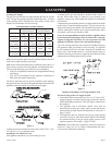
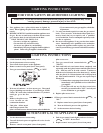
Locating Electric Supply
A 7/8" diameter knockout is provided at the bottom of the left
and right side panels. A three-prong (grounding) plug assembly is
located within the control compartment (bottom) of the furnace.
Please remove 7/8" knockout from appropriate side panel when
routing plug assembly to an electrical outlet.
Installation of Three-prong (Grounding) Plug Assembly
1. Disconnect nylon cap on 3' plug assembly from nylon plug on
wiring harness. Remove 3' plug assembly from control compart-
ment (bottom) of the furnace.
2. Remove 7/8" knockout from appropriate side panel.
3. Insert nylon cap on 3' plug assembly into the 7/8" hole in the
side panel.
4. Connect nylon cap on 3' plug assembly to nylon plug on the
wiring harness.
5. Place 7/8" strain relief bushing around the cord of the 3' plug
assembly. Insert 7/8" strain relief bushing into the 7/8" hole in
the side panel.
Attention! The 7/8" strain relief bushing is located within the same
envelope as the Installation Instructions and Owner's Manual.
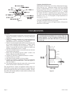
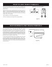
Attaching Furnace to Wall
Refer to Figure 5 for the location of the 7 1/2" diameter wall open-
ing for the furnace. After the wall opening has been located and
cut, position flue outlet on furnace in center of wall opening. When
attaching furnace to the wall remove that portion of baseboard and
molding on the wall which is behind the furnace. Attach furnace
to wall, at the outer casing top, with (2) toggle bolts provided and
to floor, at the outer casing bottom, with (2) #10 x 1 1/2" screws
provided.
Attention! The screw holes on the outer casing bottom are off-set
above the floor approximately 3/8". Do not over-tighten screws
and distort the off-set on the outer casing bottom. Distortion of
the outer casing bottom will not allow the lower front panel to be
attached to the furnace.
INSTALLATION INSTRUCTIONS (continued)