


Page 15
19562-1-0606
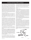
The hot surface ignitor is energized and after a 17 second warm-
up, the gas valve circuit is energized, opening the gas valve
and igniting the burners. After burning for about 30 seconds,
the circulating air blower comes on, delivering warm air to
the room. If ignition does not occur, the ignition sequence is
repeated again up to 2 more times. (3 trials for ignition-total)
3. After the furnace operates and satisfies the thermostat, the gas
valve closes and the circulating air blower continues to run for
about 2 minutes and then shuts off. The inducer blower runs
for 5 seconds and shuts off.
If for any reason ignition and operation does not occur, the
control board will blink the green fault status LED, a sequence
code, indicating what to look for as a troubleshooting guide.
If the green LED is ON but not blinking check the electronic
temperature control to verify its operation. This can be easily done
by disconnecting the 3 electronic temperature control leads from
the main furnace board and using a pig tail jumper to connect
R & W together on the board. If the furnace comes on and runs
normally the temperature control board is malfunctioning. If
the heater still does not come on, then the main furnace board
is malfunctioning. Look for any fault codes below and verify
the 3 amp fuse is not blown.
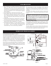
Your new furnace should provide many years of trouble free
performance, however, a yearly inspection of the burners , flue
passageways and the outlet vent assembly should be done. Be
sure all passageways are open and clear of any obstruction, or soot
build up. Be sure to shut off all power to the unit while performing
this inspection.
Periodically remove the circulating air filter and clean with water
to remove all dirt. Shake dry and reinstall in unit.
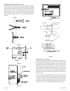
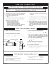
System Operation
1. This furnace has an electronic thermostat and control board
to monitor the room temperature and then control the furnace
operation to provide the best comfort and performance from a
heating appliance. To operate unit turn ON/OFF switch to ON
and then turn temperature control knob clockwise slowly till
furnace turns on. For typical room comfort, the control knob
should be pointed toward medium.
2. The furnace control board follows sequence of operation which
allows for self diagnosis in the event there is a problem. The
control then blinks a status light, a set number of blinks based
on what problem has been encountered. When the furnace is
on and there is a no fault condition, the green LED is on.
On a typical call for heat by the integral thermostat 24 VAC is
applied to the W terminal on the board.
The inducer blower circuit is energized and the inducer blower
comes on for 15 seconds pre-purging out any gas and closing
the pressure switch.
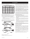
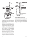
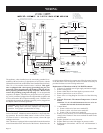
Proper Main Burner Flame
The proper main burner flame will be a blue primary (inner) flame
with a larger, lighter blue secondary (outer) blue flame.
Figure 13
Cleaning Main Burner(s)
Remove main burner(s) and apply air pressure inside the throat and
ports of the main burner(s).
Removing Main Burner(s)
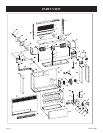
1. Remove front grill assembly.
2. Remove burner compartment access panel (2 screws).
3. Remove main burner(s) from burner compartment (2 screws
per main burner).
Removing Gas Valve
1. Remove front grill assembly.
2. Disconnect manifold union assembly at gas valve.
3. Remove (2) two 24 volt wires from gas valve. Label wires prior
to disconnection from gas valve.
4. Remove gas valve from gas valve bracket.
Removing Main Burner Orifice(s
)
1. Remove front grill assembly.
2. Remove burner compartment access panel (2 screws).
3. Disconnect manifold union assembly.
4. Disconnect manifold union assembly brackets (5 screws).
Removing Ignitor and Flame Sensor
1. Remove front grill assembly.
2. Remove ignitor from burner compartment (2 screws).
3. Remove flame sensor from burner compartment (1 screw).
Cleaning Combustion (Exchanger) Assembly
A QUALIFIED SERVICE PERSON should remove the
combustion (exchanger) assembly. Apply air pressure to the
inside of the combustion (exchanger) assembly in order to clear
all passageways.
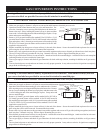
Oiling
The blower motor has an oil hole located on each end of the motor.
Use #20 motor oil only. It is best to oil the motor several times
during the heating season using 2 or 3 drops each time.
MAINTENANCE
OPERATION AND TROUBLESHOOTING