


Page 11
19562-1-0606
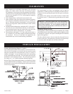
Be sure to deburr the ends with a file after cutting. Installation is
easy after cutting the wall opening secure the vent terminal box
in place using the (4) 10 x 1" hex-head screws provided. Locate
the box so that the middle exhaust tube is directed toward the
furnace exhaust outlet opening. See Figure 8. Attach the black 2"
flexible inlet air hose to the bottom 2" connector on the vent box
using a hose clamp. Secure the other end to the lower inlet air
box connector using the hose clamp. Do not kink hose. Attach the
long straight end of the 2" orange silicone exhaust elbow to the
middle vent terminal tube and rotate the elbow toward the furnace
exhaust outlet. Secure the hose to the vent box using a hose clamp.
Carefully push the furnace back closer to the wall and secure the
exhaust elbow to the 2" exhaust tube exiting the unit. Secure the
elbow in place using the last remaining hose clamp. The furnace
can now be secured to the wall.
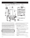
The furnace can be vented with up to a maximum length of 15'
(4.6m) including termination vent and using 2 - 90° elbows. Also,
the furnace can be vented with up to a maximum length of 10'
(3m) including termination vent and using 3 - 90° elbows. For
longer vent lengths order the vent kit, Part Number DVE-1 and
DVE-2. See Figures 11 and 12 illustrating extended vent run and
venting options.
Note: If the extended vent kit is used and the exhaust vent pipe
is run through a cold space, such as an attic or a garage, the pipe
should be insulated using 1/2" (13mm) thick fiberglass insulation
or equivalent to keep the flue products warm enough to avoid
condensation. Also, slope 1/4" (6mm) per foot (305mm) the vent
terminal horizontal run downward toward the outside of the house
to assure any condensate flow out of vent system. Horizontal
vent pipe runs of 5 feet (1.5m) or more in length may accumulate
condensation in the exhaust pipe and must, therefore, be sloped
downward to drain any condensate out of the end vent terminal.
Use straps or other suitable supports spaced every 5 feet (1.5m) to
adequately hold pipe. Be sure to avoid any low spots or sags in
pipe run. Be sure all connections are tight using the hose clamps
as shown in Figure 9, "Vent Coupling Connections."
For wall depths thicker than 10" (254mm) order the extended vent
terminal kit which will cover walls to 32" (813mm) thickness.
The vent pipes must be cut to length to assemble for desired wall
thickness.
For extended venting, it is also acceptable to use 2" (51mm) diameter
PVC or ABS pipe for the combustion air intake supply piping
only to the unit. If this is used, the pipe and fittings must conform
to ANSI and ASTM Standards D1785 for SCH. 40 PVC, D2665
for PVC-DWV, D2241 for SDR-21 and SDR-26 PVC, D2661 for
ABS-DWV and F628 for SCH. 40 ABS. Pipe cement and primer
must be used and conform to ASTM Standard D2564 for PVC or
D2235 for ABS. This PVC or ABS pipe must not be used for
the exhaust vent pipe run.
Note: Type SDR pipe is not approved for use in Canada.
For new construction installation, the intake and exhaust vent
can be run inside a wall, a vertical or horizontal distance prior to
exiting the wall. This can be done but not the preferred method of
installation due to the inability to perform periodic inspection of
the vent system. In doing this, it is important to securely seal the
vent system and slope all horizontal runs downward 1/4" (6mm)
per foot (305mm) toward the vent terminal outside to drain out
any condensate. It is also necessary to adequately support both the
exhaust and intake and to center the exhaust pipe in the wall.
Be sure to consult local codes prior to installation to verify allowable
procedures.
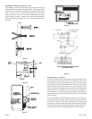
Installation of Shroud
To complete inside installation, secure furnace to the wall bracket
by attaching the two wall mounting brackets to the wall bracket
by using (2) 10 x 1/2" (13mm) hex-head screws provided (See
Figures 4 and 6). To attach the right shroud and left shroud to the
casing back, the 3/4" wide flange on the shroud must be positioned
toward the casing side. When positioned correctly, the (6) louvers
on the shroud will be facing up and the knock-out on the shroud
will be facing down. Attach the right shroud and left shroud to the
casing back with (3) 10x1/2" hex-head screws supplied in hardware
package, for each shroud. Attach top shroud to right shroud and
left shroud with (4) Phillips-head screws, supplied in hardware
package. Insert air filter into top shroud.
Attention: If the right shroud and left shroud are installed incorrectly,
with the 3/4" wide flanges facing inward, the top shroud will not
be able to be installed onto the side shrouds. The top shroud will
appear to be 2 inches, too narrow.
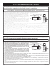
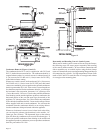
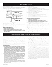
Vent Terminal (Figure 10)
Place the 6 3/8" x 6 3/8" (162mm x 162mm) black foam, wall plate
gasket within the mounting plate. The 4 3/4" (121mm) diameter
hole in the black foam gasket will allow for installation of the
concentric vent tube assembly. Slide the outside mounting plate into
place on the concentric vent tube assembly. The outside mounting
plate should seal against the face of the building and be secured
in place using (4) 10 x 1" hex-head screws. Be sure to caulk and
seal around the pipe on the exterior using high temperature exterior
grade, silicone caulk rated at 204°C/400°F. Wipe some silicone
sealant on the 2" (51mm) exhaust pipe extension. The end cap can
be pushed into place on the exhaust outlet tube.
Attention: The opening on the bottom of the end cap must be
positioned toward the ground. The opening on the bottom cannot
be pivoted to the right or left, it must be centered toward the
ground.
Figure 10
NO. 10X 11/2"
SCREWS (4)
INLETAIR
EXHAUST
AIR
12"(305mm)MIN.
ABOVE GRADE
CAULKAROUND PIPE
EXHAUST FITTING-SLIDE ONTO
2" EXHAUSTTUBEAND USERTV
SEALANTTO SECUREIN PLACE
WITH OUTLETPOINTED DOWN
AS SHOWN
FURNACE INSTALLATION (continued)