


10 SD Pump Sizing
■
Solar Water Pumping Products Catalog
■
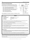
Designing a Solar Pumping System
There are many aspects of designing a solar pumping system. This guide
provides the information to correctly select a pump, controller,sensors, solar
array, wiring, and pipe. The process is broken down into the following steps:
STEP 1 - Estimate the amount of water needed per day (~GPM x 360).
STEP 2 - Calculate the TOTAL DYNAMIC HEAD (TDH).
STEP 3 - Determine the Solar Resource for your location.(See page 15)
STEP 4 - Select the pump, controller,mounting method and array.
STEP 5 - Select the correct pump cable.
STEP 6 - Select the appropriate accessories.
EXAMPLE
System Conditions
Desired TOTAL DAILY OUTPUT: 7000 liters per day (1847 gallons per day)
TOTAL DYNAMIC HEAD: 10 meters (33 feet)
Location Provides: 6-7 Sun Hours On Tilt (See page 15)
Well Diameter: 15.2 cm (6 inches)
Water Condition: sandy
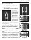
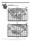
1. Select a pump that will provide the most water at the TOTAL DYNAMIC HEAD. The SD 12-30 will provide the most water.
2. Consider the sand shroud. This pump will require a sand shroud because the well is sandy.
3. Consider the diameters. The SD 12-30 with a sand shroud requires a well with a minimum diameter of 15.2 cm.
The SD 12-30, with a sand shroud, will fit in this application.
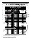
4. Using the SD 12-30 PERFORMANCE GRAPH (marked "EXAMPLE"), locate the desired liters per day (TOTAL DAILY OUTPUT)
on the lower left side of the graph, point A.
5. The system TDH equals 10 meters. Draw a line to the right until it crosses the "10 meter TOTAL DYNAMIC HEAD" line, point B.
6. The system SUN HOURS ON TILT equals 6-7. From point B, draw a vertical line upward until it crosses the
"6-7 SUN HOURS ON TILT" line, point C.
7. Draw a horizontal line through point C. Point D shows the required array wattage and point E shows the quantity and model
of Kyocera modules that will provide required amount of water. This system will provide the desired amount of water with
two KC80 solar modules. If point E does not directly intersect an array configuration, the next largest array should be selected.
IMPORTANT NOTES:
1. The array wattage listed on the graph is the total of the nameplate wattage ratings of the solar modules at STC (STANDARD
TEST CONDITIONS). The performance charts are corrected for operation in a hot climate, such as Phoenix, Arizona. In cooler
climates actual performance will be better.
2. Under no circumstances should more than 2 modules be placed in any series string. The MAXIMUM INPUT VOLTAGE for the
CD 300 Pump Controller is 50 Volts. Under certain conditions, a solar module can produce almost 25 Volts.
NOTE: The pump performance shown on the following charts represents actual system output in real applications. The performance has been
de-rated for dirt and temperature losses on the solar modules,power losses in wiring,and other system losses. Other manufactures may not take
these factors into consideration when advertising their pumps or systems. This makes comparison to other pumps difficult. These charts are
provided so that you can design a system that performs up to the expectations of the customer. In most cases,the actual system will perform
better than the charts suggest.
*For approximation purposes only.For more accurate sizing,see sizing software at www.kyocerasolar.com/products/waterpump.htm
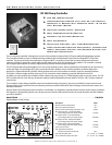
Elevation
Standing
Water Level
Draw
Down
Rack
Solar
Modules
Pump
Controller
Float
Switch
SD Drop Kit
• Submersible Cable
• Poly Tube
• Safety Rope
Submersible Cable
SS Series
Water Sensor
SD Pump
SC Motor and Wet End
Sand Shroud (SD only)
Storage
Tank
TDH = Standing Water Level + Draw Down + Elevation + 2.3 x Tank Pressure + Friction