


GKS 324.0/GKS 644.0 Installation LP gas 5
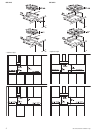
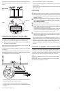
If several cook tops are installed next to each other, please observe the min-
imum distances between the cuts into the counter top as indicated in the
drawing.
Connecting the appliance to the gas supply
[
The gas cook top may only be operated if the supplied gas pressure reg-
ulator and a shut-off valve (not supplied) are connected correctly.
F
The gas supply pressure stated shall be at least an 11 inch water column
for checking the regulator setting!
Make sure the gas and the gas supply pressure are correct. The correct gas
supply pressure is 10 inch water column.
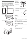
The pipe for the gas connection is located at the center of the underside of
the appliance.
The connection parts must be positioned so they can’t heat up or become
damaged while the appliance is in operation. They also can’t come into contact
with the movable parts of the kitchen elements.
– Look at the adhesive label located on the underside of the appliance to see
which type of gas the built-in cook top is set for.
– Connect the pipe for the gas connection with the enclosed adapter.
– Connect the gas pressure regulator via a rigid or a flexible conductor with
the adapter.
Make sure the regulator is installed in the right direction.
– Check the gas pressure regulator for its setting and make sure the appli-
ance isn’t leaking.
– Connect the gas pressure regulator with the shut-off valve and connect this
with the gas supply.
Leak testing
[
Before the appliance is put into operation, it must be checked by a gas
technician to make sure it’s functioning properly and there is no gas leak-
age. Leak testing of the appliance shall be conducted according to this
installation instruction!
[
Absolutely no leakage should occur, otherwise there is a danger of
fire or explosion depending upon conditions. Never use the appli-
ance if leakage is detected.
[
Do not use a flame to check for leakage!
[
The appliance and its individual shut-off valve must be disconnected from
the gas supply piping system during any pressure testing of that system
at test pressures in excess of 1/2 psi (3.5kPa).
For pressure testing of that system at test pressures equal to or less than
1/2 psi (3.5 kPa), the appliance must be isolated from the gas supply
piping system by closing its individal manual shut-off valve.
[
The maximum gas supply pressure in accordance with the inlet pressure
rating of the gas appliance pressure regulator supplied (10 inch water
column) is 13 inch water column.
– Check carefully for gas leaks immediately after the regulator has been in-
stalled and the gas turned on. Do this before attempting to operate the ap-
pliance or any other gas-burning device. Use a rich soap solution (or other
accepted leak tester) around the diaphragm flanges, bottom plate, vent
opening, seal cap pipe connections, and all other joints. Wipe clean with a
damp rag.
Connecting the appliance to the electrical supply
The appliance must be electrically grounded in accordance with local codes or,
in the absence of local codes, with the National Electrical Code, ANSI/NFPA 70.
A grounded, shockproof socket is required for electrical connection. Electrical
connection must be carried out in conformity with all local and national
codes.
The plug for the appliance is rated for 120 V / 60 Hz. The power consump-
tion is 0.7 VA.
The connection parts must be positioned so they can’t heat up or become
damaged while the appliance is in operation.
View of counter
top
Detail
Cook top
Work top