Using the WP-211DS
9
5.5 Connecting the REMOTE Connector
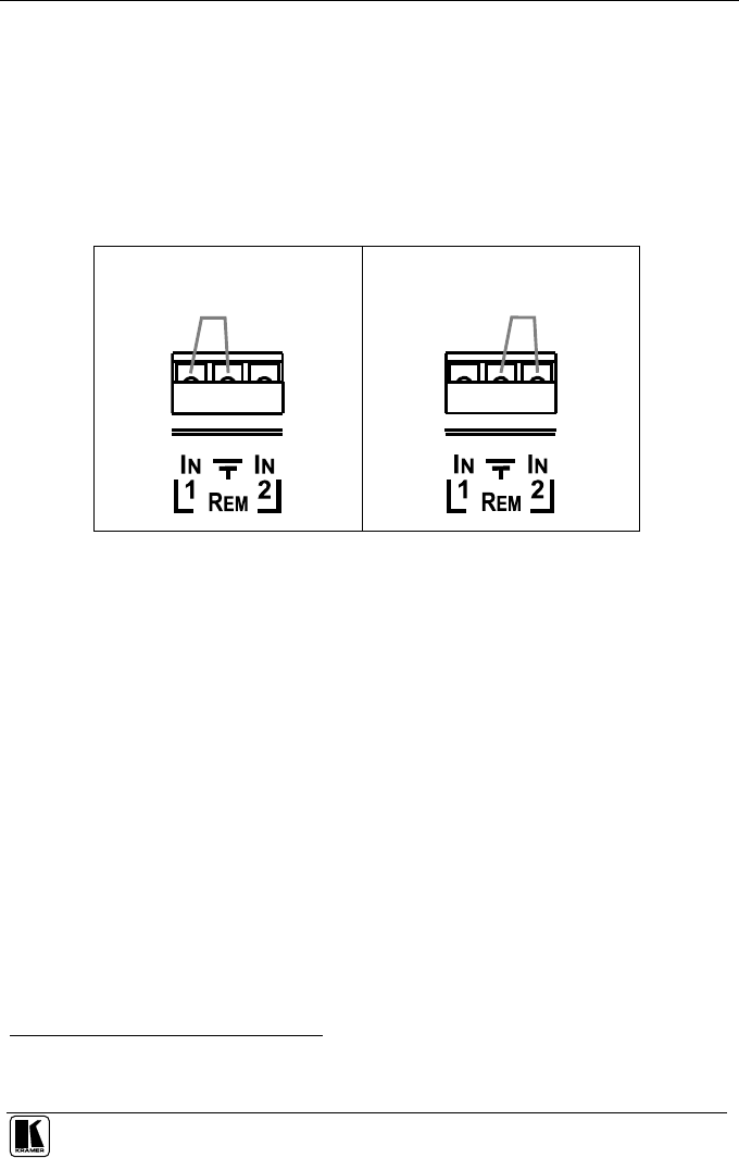
You can force the routing of one of the 2 inputs to the XGA output by remote
control. To do so, connect the appropriate REMOTE input terminal block
connector pins to a dry contact switch
1
. For example, as Figure 6 illustrates, to
route REMOTE IN 1 to the XGA output, connect PIN 1 to the Ground. To route
REMOTE IN 2 to the XGA output, connect PIN 2 to the Ground pin. Do not
connect both the REMOTE IN 1 and the REMOTE IN 2 to the Ground pin
simultaneously.
Route input 1 to the output, by
attaching PIN 1 to the Ground:
Route input 2 to the output, by
attaching PIN 2 to the Ground:
Figure 6: Remote Terminal Block Connector
When both XGA INPUT 1 and XGA INPUT 2 are connected, the signal from
XGA INPUT 1 routes to the output (factory default). However, you can force
the routing of XGA INPUT 2 to the output by attaching PIN 2 to the Ground.
Even if no input is present on XGA INPUT 1, you can force the routing of the
output from XGA INPUT 1 (displaying a blank screen) by attaching PIN 2 to
the Ground.
1 Note that the connection should be permanent, since the WP-211DS will revert to an automatic switcher when the
connection is removed
