


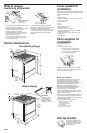
Panel B
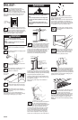
The cooktop sides of the slide-in range fit over
the cutout edge of your countertop.
If you have a square finish (flat) countertop and
the opening width is 30" (76.2 cm), no
countertop preparation is required.
Formed front-edged countertops: Must have
molded edge shaved flat 1/2" (1.3 cm) from
each front corner of opening.
Tile countertops may need trim cut back
1/2" (1.3 cm) from each front corner and/or
rounded edge flattened.
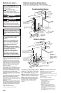
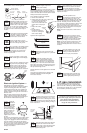
Product dimensions
Cooktop sides of range fit over
edges of countertop opening.
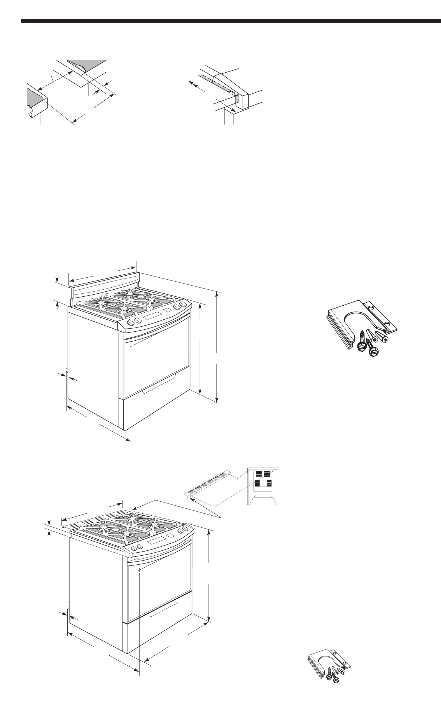
Slide-in ranges:
countertop preparation
Freestanding Range
If countertop opening width is greater than
30" (76.2 cm), adjust the 1/2" (1.3 cm) dimension.
Countertop must be level. Place level on
countertop, first side to side; then front to back.
If countertop is not level, range will not be level.
Oven must be level for satisfactory baking
conditions.
Formed or tiled countertop
trimmed 1/2" (1.3 cm) back
at front corners of
countertop opening.
30-7/8"
(78.4 cm)
1/2"
(1.3 cm)
Slide-in Range
30"
(76.2 cm)
opening
width
8-1/4"
(21 cm)
1"
(2.54 cm)
spacer
30" (76.2 cm)
range width
44-3/8"
(112.7 cm)
36-1/8"
(91.8 cm)
cooktop
height
28"
(71.1 cm)
depth
with
handle
1-1/2"
(3.8 cm)
1"
(2.54 cm)
spacer
30" (76.2 cm)
rear vent width
36-1/8"
(91.8 cm)
cooktop
height
28"
(71.1 cm)
depth
with
handle
Mobile home installation
The installation of this range must conform to the
Manufactured Home Construction and Safety
Standards, Title 24 CFR, Part 3280 (formerly the
Federal Standard for Mobile Home Construction and
Safety, Title 24, HUD, Part 280); or when such
standard is not applicable, the Standard for
Manufactured Homes Installations (Manufactured
Home Sites, Communities and Setups), ANSI
A225.1/NFPA 501A*, or with local codes.
In Canada, the installation of this range must conform
with the current standards CAN/CSA-Z240 — latest
edition**, or with local codes.
When this range is installed in a mobile home, it must
be secured to the floor during transit. Any method of
securing the range is adequate as long as it conforms
to the standards listed above.
Copies of the standards listed may be obtained from:
*
National Fire Protection Association
One Batterymarch Park
Quincy, Massachusetts 02269
**CSA International
8501 East Pleasant Valley Road
Cleveland, Ohio 44131-5575
Tools needed for
installation:
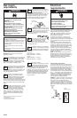
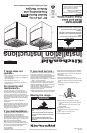
The floor anti-tip bracket must
be installed. To install the anti-tip
bracket shipped with the range,
see Panel D and the anti-tip
bracket template.
Anti-tip bracket:
Assemble the required tools and parts before starting
installation. Read and follow the instructions provided
with any tools listed here.
• level
• Phillips scewdriver
• flat-blade screwdriver or 5/16”"(7.9 mm) nut driver
• 3/8" ( 9.5 mm) ratchet
• adjustable wrench
• pliers
• hammer
• measureing tape or ruler
• hand or electric drill
wood floor: 1/8" (0.3 cm) drill bit
concrete/ceramic floor: 3/16" (0.48 cm) carbide-
tipped masonry drill bit
• L.P. gas conversion requires: pin pick up (claw
attachment)
• 5/16" nut driver
30"
(76.2 cm)
width
Parts supplied for
installation:
(Bracket must be securely mounted to sub-floor.
Thickness of flooring may require longer screws to
anchor the bracket to sub-floor.)
anti-tip
bracket
2 screws
(#10 x 1-1/2")
2 plastic
anchors
25"
(63.5 cm)
IMPORTANT:
Rear vent must not
be obstructed for
proper ventilation on
all slide-in models.
See Step 7, Panel D.
• burner grates and caps
• vent cap
• L.P. conversion orifice spud kit:
1 – 0.95 mm (0.0374") cooktop (blue)
2 – 0.67 mm (0.0264") cooktop (black)
1 – 1.05 mm (0.0413") cooktop (green)
1 – #65 (0.0350") broil burner