1. Recommended Locations for Smoke Alarms
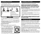
• Put smoke alarms at both ends of a bedroom hallway or large
room if the hallway or room is more than 30 ft (9.1 m) long.
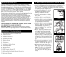
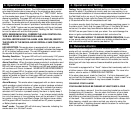
• Install Smoke Alarms on sloped, peaked or cathedral ceilings at or
within 3ft (0.9m) of the highest point (measured horizontally).
NFPA 72 states: “Smoke alarms in rooms with ceiling slopes
greater than 1 ft in 8 ft (.3m in 2.4 m) horizontally shall be locat-
ed on the high side of the room.” NFPA 72 states: “A row of
detectors shall be spaced and located within 3 ft (0.9m) of the
peak of the ceiling measured horizontally” (see figure 2).
• In the garage. Products of combustion are present when you start
your automobile.
• Less than 4” (10cm) from the peak of an “A” frame type ceiling.
• In an area where the temperature may fall below 40ºF or rise above
100ºF, such as garages and unfinished attics; this should also include
electrical boxes exposed to these environments.
• In dusty areas. Dust particles may cause nuisance alarm or failure to
alarm.
• In very humid areas. Moisture or steam can cause nuisance alarms.
• In insect-infested areas.
• Smoke alarms should not be installed within 3 ft (.9m) of the following:
the door to a kitchen, the door to a bathroom containing a tub or
shower, forced air supply ducts used for heating or cooling, ceiling or
whole house ventilating fans, or other high air flow areas.
• Kitchens. Normal cooking may cause nuisance alarms. If a kitchen
alarm is desired, it should have an alarm silence feature or be a photo-
electric type.
• Near fluorescent lights. Electronic “noise” may cause nuisance alarms.
• Smoke alarms are not to be used with detector guards unless the
combination (alarm and guard) has been evaluated and found suitable
for that purpose.
3. Installation Instructions
WIRING REQUIREMENTS
• This smoke alarm should be installed in a U.L. listed or recognized
junction box. The mounting bracket is equipped to accommodate a
3.5 inch hole spacing on a round electrical box and a double-gang
rectangular electrical enclosure. All connections should be made by a
qualified electrician and all wiring used shall be in accordance with
articles 210 and 300.3(B) of the U.S. National Electrical Code
ANSI/NFPA 70, NFPA 72 and/or any other codes having jurisdiction in
your area. This unit consumes four cubic inches of interior space of
the junction box volume. This figure should be used when calculating
junction box volume.
• The multiple station interconnect wiring to the alarms must be run in
the same raceway or cable as the AC power wiring. In addition, the
resistance of the interconnect wiring shall be a maximum of 10 ohms.
• The appropriate power source is 120 Volt AC Single Phase supplied
from a non-switchable circuit which is not protected by a ground fault
interrupter.
•
WARNING: This alarm cannot be operated from power derived from
a square wave, modified square wave or modified sine wave inverters.
These types of inverters are sometimes used to supply power to the
structure in off grid installations, such as solar or wind derived power
sources. These power sources produce high peak voltages that will
damage the alarm.
Wiring Instructions for Quick Connect Harness
CAUTION! Turn off the main power circuit before wiring the
alarm
• When alarms are interconnected, all interconnected units must be
powered from a single circuit.
• A maximum of 18 Kidde devices may be interconnected in a multiple
station arrangement. The interconnect system should not exceed the
NFPA interconnect limit of 12 smoke alarms or 18 alarms {12 smoke
and 6 other (heat, carbon monoxide, or similar alarms)}.
• When mixing models which have battery backup (i12040, i12060,
i12080, 1275, 1276, 1285, 1296, PE120, PI2000, KN-COSM-IB, KN-
SMFM-I, RF-SM-ACDC, HD135F, KN-COB-IC, KN-COP-IC) with models
without battery backup, (i1220, 1235, KN-COSM-I, 120X,
SM120X,CO120X, SL177i) be advised that the models without battery
backup will not respond during an AC power failure.
2. Locations To Avoid


