


4.OPERATION AND TESTING
OPERATION: The smoke alarm is operating once A.C. power is applied, fresh batteries are installed
and testing is complete. When the smoke alarm ionization chamber senses products of combustion,
the horn will sound a loud (85db) temporal alarm until the sensing chamber is cleared of smoke parti-
cles.
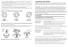
HUSH CONTROL: The “HUSH” feature has the capability of temporarily desensitizing the alarm circuit
for approximately 7 minutes. This feature is to be used only when a known alarm condition, such as
smoke from cooking, activates the alarm. The smoke alarm is desensitized by pushing the “HUSH”
button on the smoke alarm cover. If the smoke is not too dense, the alarm will silence immediately
and “chirp” every 30 -40 seconds for approximately 7 minutes. This indicates that the alarm is in a
temporarily desensitized condition. The smoke alarm will automatically reset after approximately 7 min-
utes and sound the alarm if particles of combustion are still present. The “HUSH” feature can be used
repeatedly until the air has been cleared of the condition causing the alarm. Pushing the test/reset but-
ton on the alarm will end the hush period.
NOTE: DENSE SMOKE WILL OVERRIDE THE HUSH CONTROL FEATURE AND SOUND A CON-
TINUOUS ALARM.
CAUTION: BEFORE USING THE ALARM HUSH FEATURE, IDENTIFY THE SOURCE OF THE
SMOKE AND BE CERTAIN A SAFE CONDITION EXISTS.
LED INDICATORS: This smoke alarm is equipped with red and green LED indicators. The red LED is
located under the test button and has two modes of operation.
Standby Condition The red LED will flash every 30-40 seconds to indicate that the smoke
alarm is operating properly.
Alarm Condition When the alarm senses products of combustion and goes into alarm,
the red LED will flash rapidly (one flash per second). The rapid flashing
LED and pulsating alarm will continue until the air is cleared.
WHEN UNITS ARE INTERCONNECTED, only the red LED of the alarm which senses the smoke or is
being tested (the originating unit) will flash rapidly. All other units in the interconnect system will sound
an alarm but their red LED’s will NOT flash rapidly.
The green LED is located under the “Hush” button and has two modes of operation.
Standby Condition The green LED will be steady on, indicating the presence of AC power.
Alarm Condition This smoke alarm is equipped with an alarm memory which provides a
visual indication when an alarm has been activated. A flashing green LED
indicates the memory condition. The memory will remain activated until it is
reset by pushing the test button.
In an interconnected installation only the memory of the originating alarm will be activated.
TESTING: Test by pushing the test button on the cover and hold it down for a minimum of 2 seconds.
This will sound the alarm if all the electronic circuitry, horn and battery are working. If no alarm sounds,
check the fuse or circuit breaker supplying power to the alarm circuit. If the alarm still does not sound,
the unit has defective batteries or other failure. DONOT use an open flame to test your alarm, you
could damage the alarm or ignite combustible materials and start a structure fire.
TEST THE ALARM WEEKLY TO ENSURE PROPER OPERATION. Erratic or low sound coming from
your alarm may indicate a defective alarm, and it should be returned for service (see Section 12).
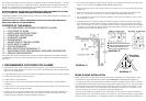
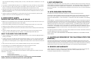
5. Plug the A.C. QUICK CONNECTOR into the back of the alarm (see Figure 3), making sure that the
locks on the connector snap into place. Then push the excess wire back into the electrical box
through the hole in the center of the trim ring.
6. If you have finished all the WIRING, BATTERY INSTALLATION AND TRIM RING MOUNTING STEPS,
you can install the alarm on the trim ring. Alignment marks are provided on the side of the alarm
and on the trim ring (see Figure 4).
7. Install the alarm on the trim ring with the indicating marks aligned and rotate the alarm in the direc-
tion of the “ON” arrow on the cover until the alarm snaps in place (see Figure 4).
8. Turn on the A.C. power. The green A.C. Power On Indicator should be lit when the alarm is operat-
ing from A.C. power.
TAMPER RESIST LOCKING PIN: To make your smoke alarm somewhat tamper resistant, a locking
pin has been provided with your alarm. Using this pin will deter children and others from removing the
alarm from trim ring. To use the pin, insert it into the hole in the side of the alarm after the alarm has
been installed on the trim ring (see Figure 5)
NOTE the tamper resist pin will have to be removed in order to change the batteries. Use a long nose
pliers to pull the pin out of the hole. It is now possible to remove the alarm from the trim ring.
After installation, TEST your alarm by pressing and holding the test button for several seconds, or by
blowing smoke into the alarm. This should sound the alarm.
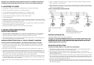
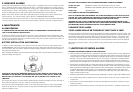
Rectangular Plaster Ring Circular Plaster Ring Octagonal Electrical Box
FIGURE 2. SELECT CORRECT MOUNTING HOLES ON TRIM RING
To remove A.C.
connector,
squeeze
locking arms
and pull
Alignment marks
Install Remove
Tamper resistant
locking pin
FIGURE 3. FIGURE 4. FIGURE 5.