


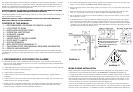
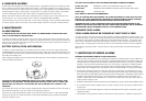
•Figure 1 illustrates interconnection wiring. Improper connection will result in damage to the alarm,
failure to operate, or a shock hazard.
•Make certain alarms are wired to a continuous (non-switched) power line. NOTE: Use standard UL
listed household wire (18 gauge or larger as required by local codes) available at all electrical supply
stores and most hardware stores.
FIGURE 1 INTERCONNECT WIRING DIAGRAM
WIRES ON ALARM HARNESS CONNECTED TO
Black Hot Side of A.C. Line
White Neutral Side of A.C. Line
Red Interconnect Lines (Red Wires) of Other
Units in the Multiple Station Set up
BATTERY INSTALLATION
See MAINTENANCE (Section 6) for battery installation.
CAUTION! IF THE BATTERY REMINDER FINGER IS NOT HELD DOWN IN THE BATTERY COM-
PARTMENT BY THE BATTERY, THE BATTERY DOOR WILL NOT CLOSE, THE A.C. QUICK CON-
NECTOR WILL NOT ATTACH TO THE ALARM, AND THE ALARM WILL NOT ATTACH TO THE
TRIM RING (SEE SECTION 6, FIGURE 6).
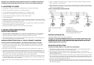
MOUNTING INSTRUCTIONS
CAUTION: THIS UNIT IS SEALED. THE COVER IS NOT REMOVABLE!
1. Remove the trim ring from the back of the alarm by holding the trim ring and twisting the alarm in
the direction indicated by the “OFF” arrow on the alarm cover.
2. After selecting the proper smoke alarm location as described in Section 1 and wiring the A.C.
QUICK CONNECT harness as described in the WIRING INSTRUCTIONS, attach the trim ring to the
electrical box (see Figure 2).
3. Use a screwdriver to punch out only the pair of holes in the trim ring that match your type of electri-
cal box or plaster ring. Mount the trim ring to the electrical box, using the appropriate holes. NOTE:
Use the circle, square and octagon markings near each mounting hole in the trim ring to help you
select the correct mounting holes (see Figure 2).
4. Pull the A.C. QUICK CONNECTOR through the center hole in the trim ring and mount the ring, mak-
ing sure that the mounting screws are positioned in the small ends of the keyholes before tightening
the screws (see Figure 2).
Optional Accessory
WARNING: TEST YOUR SMOKE ALARM OPERATION AFTER R.V. OR MOBILE HOME VEHICLE
HAS BEEN IN STORAGE, BEFORE EACH TRIP AND AT LEAST ONCE A WEEK DURING USE.
2.LOCATIONS TO AVOID
•In the garage. Products of combustion are present when you start your automobile.
• Less than 4” (10cm) from the peak of an “A” frame type ceiling.
•In an area where the temperature may fall below 40ºF or rise above 100ºF.
•In dusty areas. Dust particles may cause nuisance alarm or failure to alarm.
•In very humid areas. Moisture or steam can cause nuisance alarms.
•In insect-infested areas.
•Smoke alarmsshouldnotbeinstalledwithin3ft(.9m)ofthefollowing:thedoorto akitchen,thedoor
to abathroom containing atuborshower,forced air ductsusedforheatingorcooling,ceilingorwhole
house ventilatingfans,orotherhighairflowareas.
•Kitchens. Normal cooking may cause nuisance alarms. If a kitchen alarm is desired, it should have
an alarm silence feature or be a photoelectric type.
• Near fluorescent lights. Electronic “noise” may cause nuisance alarms.
3.INSTALLATION INSTRUCTIONS
WIRING REQUIREMENTS
• This smoke alarm should be installed on a U.L. listed or recognized junction box. All connections
should be made by a qualified electrician and must conform to article 760 of the U.S. National
Electrical Code, NFPA 72 and/or any other codes having jurisdiction in your area.
• The appropriate power source is 120 Volt A.C. Single Phase supplied from a non-switchable circuit
which is not protected by a ground fault interrupter.
WIRING INSTRUCTIONS FOR A.C. QUICK CONNECT HARNESS
CAUTION! TURN OFF THE MAIN POWER TO THE CIRCUIT BEFORE WIRING THE ALARM.
• For alarms that are used as single station, DO NOT CONNECT THE RED WIRE TO ANYTHING.
Leave the red wire insulating cap in place to make certain that the red wire cannot contact any
metal parts or the electrical box.
•When alarms are interconnected, all interconnected units must be powered from a single circuit.
•A maximum of 24 Lifesaver devices may be interconnected in a multiple station arrangement. The
interconnect system should not exceed the NFPA interconnect limit of 12 smoke alarms and/or 18
alarms total (smoke, heat, carbon monoxide, etc.) With 18 alarms interconnected, it is still possible
to interconnect up to a total of 6 remote signaling devices and/or relay modules.
•When mixing models which have battery backup (1275, 1275H, 1285, PE 120, HD135F) with mod-
els without battery backup, (1235, 120X, SL177I) be advised that the models without battery back-
up will not respond during an AC power failure.
• The maximum wire run distance between the first and last unit in an interconnected system is 1000
feet.