


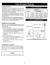
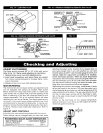
CIRCULATING PUMP
Every forced hot-water system requires a circulating pump. A separate pump or zone valve is required for each zone, if you
have a two or more zone system. This pump must have the capacity to provide the circulation required by your system.
The pump is connected into the return main just ahead of the boiler. It is also wired to the electrical system.
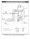
VENT DAMPER
This product is an automatic, motorized stack damper that has been developed to increase the efficiency of heating systems
by reducing standby losses from the heating apparatus and the conditioned air space. The damper closes the chimney vent
when the burner is off and fully opens it when combustion is required.
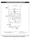
L7148F ELECTRONIC AQUASTAT CONTROL
The L7148F Electronic Aquastat Control is an immersion type hydronic controller that provides high limit protection and
controls the circulator, gas valve and vent damper. The L7148F Control does not provide a low limit function. An external
transformer (ATI50-B), appropriately sized for this application; a sensor (209659A) and an immersion well are required for
aquastat operation. The L7148F Electronic Aquastat Control has three states of operation: Normal, High-Limit, and Reset:
(The control moves back and forth between the normal and high-limit states, as needed. However, the control only enters
the reset state when there is an abnormal condition such as an internal error or shorted sensor). In the L7148E system, the
circulator and burner are on any time there is a thermostat call for heat, unless the boiler water temperature exceeds the
high limit setting. (The high-limit switch shuts off the burner (B1, B2 output) when the boiler water temperature exceeds the
high limit setting). The water temperature limit control is adjustable and may be set as necessary. Turn the High-Limit dial
on the control to the desired setting. It may be set as low as 130° F., 140° F. is recommended (refer to page 5 for "LOW
DESIGN WATER TEMPERATURE SYSTEMS BELOW 140° F.) or as high as 240 ° F. (we recommend not to exceed 220 ° F.,
refer to page 19 "ADJUST LIMIT CONTROLS'_. This depends on the type and amount of radiation involved and weather
conditions.
ROLLOUT SWITCH (FLAME ROLLOUT SAFETY SHUTOFF)
The rollout switch isa temperature-sensitive fuse link device. It is located on the boiler base just outside the fire box. In
the event of heat exchanger flueway blockage causing flame to roll out of the fire box, the fuse does not change in
appearance when blown. If the rollout switch blows, it must be replaced with an exact replacement. Check heat exchanger
flueways for blockage when restoring system to operating condition. DO NOT operate system without a rollout switch.
SPILL SWITCH (BLOCKED VENT SAFETY SHUTOFF)
The spill switch is a manual reset disc thermostat with a fixed setpoint (340 ° F), and normally closed contacts. It is located
at the relief opening of the integral draft diverter. In the event of chimney or venting system blockage causing products of
combustion to spill out of the relief opening, the spill switch disc heats up and the spill switch contacts open, shutting down
the flow of gas to the main burners by removing power to the gas valve. In the event that the spill switch contacts open,
the reset button on the back of the switch will pop up. The spill switch must be reset manually, after the switch has cooled
off, by pushing the reset button down. Check the venting system and chimney for blockage when restoring the system to
operating condition. DO NOT operate the boiler without a spill switch.
18