


WARNING
TURN OFF ELECTRICAL POWER AT FUSE BOX BEFORE MAKING ANY LINE VOLTAGE CONNECTIONS.
FOLLOW LOCAL ELECTRICAL CODES.
II I
All electrical work must conform to local codes as well as the National Electrical Code, ANSI/NFPA-70, latest revision. In
Canada, electrical wiring shall comply with the Canadian Electrical Codes, CSA-C22.1 and .2.
ELECTRIC POWER SUPPLY
Prior to making any line voltage connections, service switch at boiler should be in the offpnsition and the power turned offat
the fuse box.
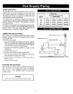
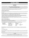
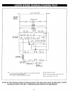
Run a separate 120 volt circuit from a separate over current protection device in the electrical service entrance panel. This
should be a 15 ampere circuit. A ser+ice switch has been provided and should be mounted to the Junction box located on the
exterior boiler jacket. See Fig. 13-1 for diagram showing power supply connection points.
The boiler, when installed, must be eleotrically grounded in accordance with the requirements of the authority having
jurisdiction or, in the absence of such requirements, with the National Electrical Code, ANSI/NFPA-70, latest revision. In
Canada, electrical wiring shall comply with the Canadian Electrical Codes, CSA-C22.1 and .2.
Run a 14 gauge or heavier copper wire from the boiler to a grounded connection in the service panel or a properly driven and
electrically grounded ground rod.
INSTALL YOUR THERMOSTAT
The thermostat location has an important effect on the operation of your boiler system. BE SURE TO FOLLOW THE
INSTRUCTIONS INCLUDED WITH YOUR THERMOSTAT.
Locate the thermostat about five feet above the floor on an inside wall. It may be mounted directly on the wall or on a
vertical mounted outlet box. It should be sensing average room temperature. Avoid the Following:
DEAD SPOTS:
Behind doors
Comers and alcoves
COLD SPOTS:
Concealed pipes or ducts
Stairwells - drafts
Unheated rooms on
other side of wall
HOT SPOTS:
Concealed pipes Lamps
Fireplace Direct sunlight
TV sets Kitchens
Radios
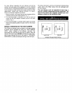
Set heat anticipator at 0.1 amps. Connect 24 volt thermostat leads to the two(2) yellow wires located in service switch
junction box, located on outer jacket of boiler. See Fig.13-1 for service switch junction box and thermostat field wiring
connections.
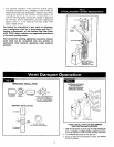
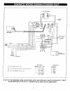
VENT DAMPER WIRING
The boiler is equipped with a factory wired harness with 4 pin molex plug, that plugs into a 4 pin molex receptacle inside the
vent damper operator. The vent damper must be connected for the boiler to operate. Wiring diagrams follow for the various
different models.
CAUTION
Label all wires prior to disconnection when servicing controls. Wiring errors can cause improper and
dangerous operation. Verify proper operation after servicing.
11