


5
-- STEP 1: INSTALL COLD WATER SUPPLY SADDLE VALVE --
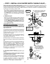
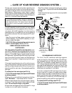
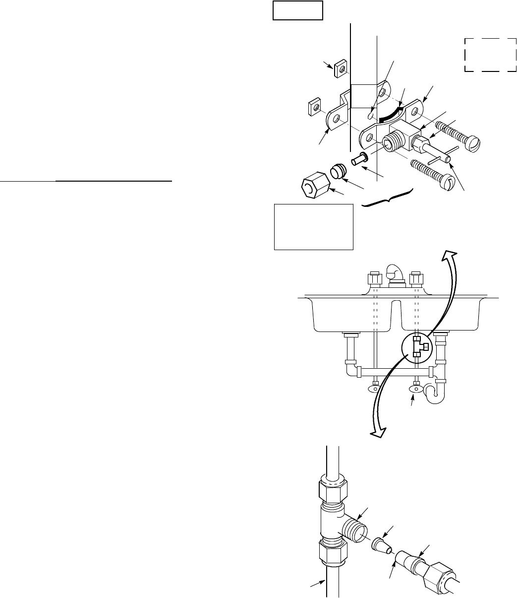
Check and comply with local plumbing codes as you plan, then install a cold feed (supply) water fitting. The
fitting must provide a leak-tight connection to the RO 1/4” tubing (see FIG. 8, page 8). A typical connection,
using the included saddle valve is shown in FIG.3 -A below. An optional connection, using standard plumb-
ing fittings (not included), is shown in B.
Note: Codesin the state of Massachusetts require instal-
lation by a licensed plumber, and do not permit the use
of the saddle valve. For installation, use plumbing
code 248-CMR of the Commonwealth of Massa-
chusetts.
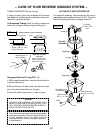
A. SADDLE VALVE
Note: This valve has a cutting pin and will pierce a
holeincoppertubingorplastic pipe.If installingon
ironpipe, you have todrill a 1/8” hole for the pierc-
ing pin. Read the following danger note and be
sureto turn off water to thepipe and to drain water
from it before drilling.
DANGER(if drilling metal pipe): To protect your-
self from serious injury or fatal shock, use a battery
powered hand drill only to make the hole. Do not
use an electric drill.
1.Close the housemainwatershutoffvalveandopen
faucets to drain water from the sink cold water pipe.
2. Observing above note and caution, drill the 1/8”
diameter hole in iron pipe.
3. Looking at figure 3A, turn the valve into clamp X
and tighten (maybe already assembled). Turn the
valve handle all the way out.
4. Place the seal on the inside of clamp X as shown.
Be sure the cutting pin does not stick out beyond the
seal.
5. Place clamp X and Z around the pipe and secure in
place with 2 screws. If you predrilled a 1/8” hole,
align the cutting pin with it. Tighten both screws
evenly, but do not overtighten. Clamp Z will either
have threaded screw holes, or 2 nuts are included.
6. Carefully turn the handle inward to pierce a hole
in the copper or plastic pipe.
B. OPTIONAL PIPE FITTINGS (compression type
shown)
Note: Be sure to turn off the water supply and open
a low faucet to drain the pipe.
Complying with plumbing codes, install a fitting on
the kitchen cold water pipe to adapt 1/4” ODtubing.
A typical connection is shown in figure 3B. If
threaded fittings are used, be sure to use pipe joint
compound or Teflon tape on outside threads.
handle
clamp X
clamp Z
nut (2) --- not req’d
with all types of
clamp Z
seal
pre---drill
1/8” hole
for iron pipe
cold water
shutoff
valve
Check local
codes for
approval
nut
insert
ferrule
A. WATER SUPPLY CONNECTION
(using included saddle valve)
B. WATER SUPPLY
TYPICAL CONNECTION
(using compression fitting)
ferrule
insert
1/4” compression
fitting
cold
water
pipe
1/4” tubing to
RO inlet (see step
2, on page 8)
use to connect
tubing, step 2,
on page 8
FIG. 3
-- parts not included --
See note on codes
in the state of
Massachusetts,
above left.