


36
Service Tech Information
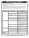
TROUBLESHOOTING
VALVE POSITION INDICATORS:
Depending on the valve position, the following indica-
tors show in the display:
Indicator Valve Position
Serv.....................................Service
Fill........................................Fill
Brine....................................Brining/Brine Rinse
Bkwsh..................................Backwash
Rinse...................................Fast Rinse
When the valve is rotating from one cycle to another,
both indicators flash. For example, if the valve is in
transition between fill and brining, both Fill and Brine
flash. Upon reaching brining position, Fill goes off and
Brine is on steady. The time display shows the minutes
of the cycle remaining.
NOTE: If the faceplate is left in a diagnostic display
(or a flashing display when setting times or hard-
ness), present time automatically returns if a button
is not pressed within 4 minutes. To return to the
diagnostic display, repeat step 1.
OTHER INFORMATION
While in this diagnostic screen, the following information
is available and may be beneficial for various reasons.
This information is retained by the computer from the
first time electrical power is applied to the faceplate.
• Press and hold the UP button to display the number of
days this faceplate has had electrical power applied.
• Press and hold the DOWN button to display the num-
ber of regenerations initiated by this faceplate since
the model code number was entered.
• Press the REGENERATION button to advance the
valve to each position and observe the switch and
position indicators to verify component operation, or to
possibly isolate a defect.
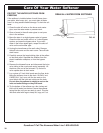
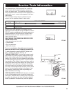
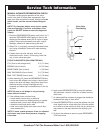
• Press and hold the SELECT button for 3 seconds until
either S 25 or S 26 shows in the display, see Fig. 51.
This code identifies the softener nominal capacity
size. If the wrong number shows, the softener will
operate on incorrect programming. Do the following as
needed.
S 25 or S 26 does show: Press the SELECT button
to return to the present time display.
To change the number: Press the UP or DOWN but-
ton until the correct code shows. Then, press the
SELECT button and reset the timer.
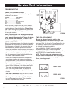
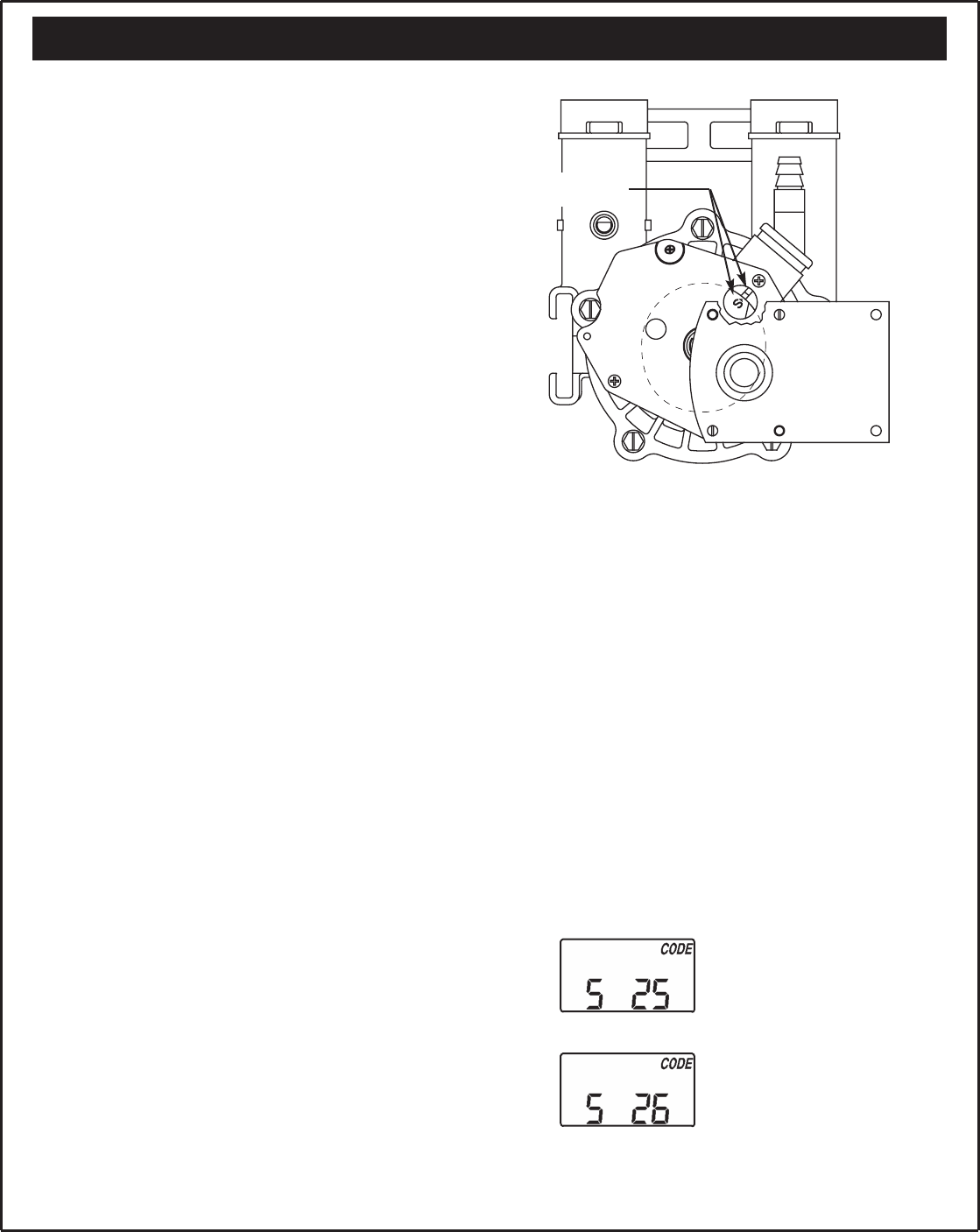
TIMER PWA REPLACEMENT
Be sure the valve is in service position when
replacing the timer PWA (observe valve cycle indi-
cator). If after installing and programming the replace-
ment timer PWA, the valve is not in service position, do
the following to assure correct cycle orientation, or tim-
ing, between the faceplate and valve.
Use the MANUAL ADVANCE procedures with the
REGENERATION button, advance through the
recharge cycles until the valve stops in service position,
and RECHARGE no longer flashes in the display.
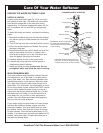
NOTE: The valve motor may automatically drive
through several valve positions while searching for
service. If an error code occurs, unplug the trans-
former, then plug in again.
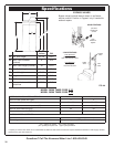
Position markers
(Valve in service)
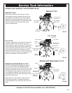
MODEL 38306
MODEL 39306
MOTOR
FIG. 51
FIG. 50
Questions? Call The Kenmore Water Line 1-800-426-9345
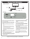
OUT
IN