


17
The appliance and its individual shut-off valve shall be
disconnected from the gas supply piping system during any
pressure testing of that system at test pressures in excess of 1/
2 pound per square inch (3.5 kPa). It shall be isolated from the
gas supply piping system by closing its individual manual shut-
off valve during any pressure testing of the gas supply piping
system at test pressures equal to or less than 1/2 pound per
square inch (3.5 kPa).
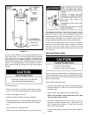
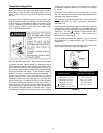
Connecting the gas piping to the gas control valve of the water
heater can be accomplished by either of the two methods shown
in Figures 19 and 20.
Sediment Traps
Contaminants in the gas lines may cause improper operation of
the gas control valve that may result in fire or explosion. Before
attaching the gas line be sure that all gas pipe is clean on the
inside. To trap any dirt or foreign material in the gas supply line,
a drip leg (sometimes called a sediment trap) must be
incorporated in the piping. The drip leg must be readily
accessible. Install in accordance with the Gas Piping section.
Refer to the current edition of the National Fuel Gas Code,
ANSI Z223.1/NFPA 54.
A sediment trap shall be installed as close to the inlet of the
water heater as practical at the time of water heater installation.
The sediment trap shall be either a tee fitting with a capped
nipple in the bottom outlet or other device recognized as an
effective sediment trap. If a tee fitting is used, it shall be installed
in conformance with one of the methods of installation, shown
in Figures 19 and 20.
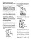
FIGURE 19. GAS PIPING WITH FLEXIBLE CONNECTOR.
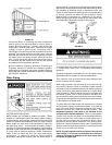
FIGURE 20. GAS PIPING WITH ALL
BLACK IRON PIPE TO GAS CONTROL.