


13
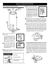
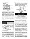
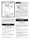
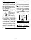
Figure 15 shows the typical attachment of the water piping to
the water heater. The water heater is equipped with 1” NPT
(75 gallon models) or 1.25” NPT (100 gallon models) water
connections.
TYPICAL INSTALLATION
FIGURE 15.
NOTE: If using copper tubing, solder tubing to an adapter
before attaching the adapter to the water connections. Do
not solder the water lines directly to the water connections
on the tank. It will harm the dip tube and damage the tank.
• Look at the top cover of the water heater. The water outlet is
marked “HOT”. Put two or three turns of teflon tape around
the exposed end of the NPT threaded nipple. Connect the
hot water pipe to the hot water outlet on the water heater.
Please note that adapters may be needed to match existing
piping.
• Look at the top of the water heater. The cold water inlet is
marked “COLD”. Put two or three turns of teflon tape around
the exposed end of the NPT threaded nipple. Connect the
cold water pipe to the cold water inlet of the water heater.
Please note that adapters may be needed to match existing
piping.
NOTE: This water heater is super insulated to minimize
heat loss from the tank. Further reduction in heat loss
can be accomplished by insulating the hot water lines
from the water heater.
Temperature-Pressure Relief Valve
This heater is provided with a properly certified combination
temperature - pressure relief valve by the manufacturer.
The valve is certified by a nationally recognized testing
laboratory that maintains periodic inspection of production of
listed equipment of materials as meeting the requirements for
Relief Valves and Automatic Gas Shut-off Devices for Hot Water
Supply Systems, ANSI Z21.22 and the code requirements of
ASME.
If replaced, the valve must meet the requirements of local
codes, but not less than a combination temperature and
pressure relief valve certified as indicated in the above
paragraph.
The valve must be marked with a maximum set pressure not
to exceed the marked hydrostatic working pressure of the
water heater (150 psi = 1,035kPa) and a discharge capacity
not less than the water heater input rate as shown on the
model rating plate.
For safe operation of the water heater, the relief valve must not
be removed from its designated opening nor plugged.
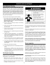
The temperature-pressure relief valve must be installed directly
into the fitting of the water heater designed for the relief valve.
Position the valve downward and provide tubing so that any
discharge will exit only within 6 inches (153 mm) above, or at
any distance below the structural floor, see Figure 16. Be certain
that no contact is made with any live electrical part. The
discharge opening must not be blocked or reduced in size under
any circumstances. Excessive length, over 30 feet
(9.14 m), or use of more than four elbows can cause restriction
and reduce the discharge capacity of the valve.