


Installation Instructions (cont'd)
AWARNING
. Tbe appEanceaed its individueJsbetoffvalve must be discon-
nected from the gassupplypipingsym_n during any pressure
testing of the gas system at test pressures in excess of 'A
poundper squareinch(3.5k1%).
. The appliancemustbeisobtedfromffmgassupplypipingsys-
tem bydosing i_ individual manual shutoffvalve during any
pr--_ure tosting of the gas supplypipingsystem at test pres-
suresequal or lessthan _ pound persquare inch(3.SkPa_
I AWARNING I
Use pipe joint compound or teflon tape marked as being
resistantto tbeactionofpeU'oleum[Propane(LR)] gases. I
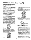
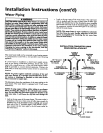
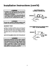
GAS PIPING WITH
FLEXIBLE CONNECTOR
GROUND
UNION(Optional)
LOOP
DRIP LEG
(Sedimenttrap)
CAP
GAS
CONTROL
VALVE
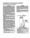
SEDIMENT TRAP
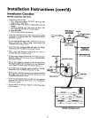
A sediment trap shall be installed as close to the inlet of the
water heater as practical at the time of water heater installation.
The sediment trap shall be either a tee fitting with a capped nip
pie in the bottom outlet or other device recognized as an effec-
tive sediment trap. If a tee fitting is used, it shall be installed in
conformance with one of the methods of installation shown
below.
Connecting the gas piping to the gas control valve of the water
heater can be accomplished by either of the two methods shown,
AWARNING
Contaminonts in the gaslines may causeimproper operatinn
of the gas €ontrol valve that may rasult in Ere or explosion.
Bofore attaching tbe gasline be sure that aflIps pipe is dean
on the imide. To trap any dirt or foreign n_ter_l in the gas
supply line, a drip leg (sometimes called a sediment trap)
must be incorporated in the piping. The drip leg must be
readily accessible.Installin accordance with the '_,as Piping"
section. Refer to the latest edition of the National Fuel Gas
Code, ANSI 7.223.1, also referred to asNFPA 54.
GAS PIPING WITH ALL BLACK IRON
PIPE TO GAS CONTROL
GROUND IO!NT -_ BLACK PIPE
UNION(Op_on_)__ /
CO NTVALvP_EOL
3"
_-J CAP
15