


Installation Instructions (cont'd)
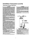
AWARNING
• The appliance and its individualshutoff valvemust be discon-
ne_edfnxnthetm sup_yp_ngsystemduringanypr_u_
testing of the gas systemat test pressures in excessof V,
poundper squareinch(3.Sl#a).
• Tbe appliance mustbe isolatedfrem the gassopply pipingsys-
tem by dosingits individualmanualshutoff valveduring any
pressuretestieg of the gassupplypipingsystem at test pre_
sumsequalor lessthan ½poundper squareinch(3.SkPa).
AWARNING I
Use pipe joint compound or teflon tape marked as being I
resistantto the action of peWoleum[Propane (LR)] gases. I
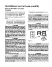
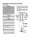
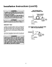
SEDIMENT TRAP
A sediment trap shall be installed as cldse to the inlet of the
water heater as practical at the time of water heater installation.
The sediment trap shall be either a tee _tting with a capped nip-
ple in the bottom outlet or other devicerecognizedas an effec-
tive sediment trap. Ira tee 8tting is used, it shaUbe installed in
conformance with one of the methods of installation shown
below.
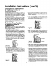
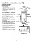
Connecting the gaspiping to the gas control valveof the water
heater canbe accomplished by either of the two methods shown.
AWARNING
Contaminants inthe gaslines may causeimproper operation
of the gas con_ol valve that may result in tim or explesion.
Befora attaching the gasline be sum thnt =11gaspipe isdexn
on the ieside.To trap any dirt or fo_qgn material in the gas
supply line, a drip leg (sometimes called a sediment trap)
must be incorporated in the piping. The drip leg must be
readilyaccessible.Installin accordancewith the "Gas Piping"
section.Rofer to the Intest edition of the National Fuel Gas
Cede, ANSI Z223.1, also rofemsdto as NFPA 54.
GAS PIPING WITH
FLEXIBLE CONNECTOR
FLEXIBLE GAS CONNECTOR
LABELEDASCOMPLYING
c°NT °
VALVE
GAS PIPING WITH ALL BLACK IRON
PIPE TO GAS CONTROL
GROUND JOINT BLACK PIPE
UNION(Optional)
DRIP LEG
(Sedimenttrap)
GAS
CONTROL
VALVE
CAP
15