


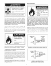


Theseguidelinesshouldbeusedbyaqualifiedserviceagent.CallSearsServiceat1-800-4-MY-HOME_(1-800-469-4663)
forassistance.Informtheassociatethatthisisa"FlammableVaporIgnitionResistant"Product.
IIIIIiI .I l_lll I II ilt,."lt,;.ilil. I-;-lll-:.l.
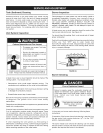
OFF
GAS
VALVE
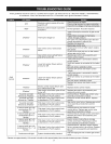
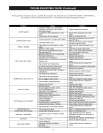
1 flash *
2flashes *
3flashes *
4flashes *
5flashes *
6flashes *
7flashes *
8flashes *
6 second solid light
followed by 4 flashes *
6 second solid light
followed by 7 flashes *
6 second solid light
followed by 8 flashes *
6 second solid light with
combinations of 4 + 7
flashes *
6 second solid light with
combinations of 4+ 8
flashes *
6 second solid light with
combinations of 7 + 8
flashes *
gI_I,.,UUIIII., I.,UIILIUI I[IULILII_ l.lll UI t.)IIUL
assembly off.
Electronic control module is powered
and pilot lit.
Thermopile voltage low.
Gas control valve or tank sensor
failure.
Gas control valve overheat failure
(pilot off or burner off).
Lower tank sensor failure (pilot on
and burner off).
Upper tank sensor failure (pilot on
and burner off).
Electric control module failure (pilot
on or off and burner off).
Gas control valve failure (pilot off and
burner off).
Pilot stays lit only when control knob
is depressed in PILOT position.
Pilot stays lit only when control knob
is depressed in PILOT position.
Pilot stays lit only when control knob
is depressed in PILOT position.
Pilot stays lit only when control knob
is depressed in PILOT position.
Pilot stays lit only when control knob
is depressed in PILOT position.
Pilot stays lit only when control knob
is depressed in PILOT position.
6 second solid light with
combinations of 4 + 7 + 8 Pilot stays lit only when control knob
flashes * is depressed in PILOT position.
Continuous solid light System shutdown/safety interlock.
__11111i[o]
Check for power to heater.
Check wiring harness for proper connection.
Check for line voltage at harness connectors.
Normal operation. No action required.
inspect thermopile connection to gas control
valve.
inspect flame coverage on thermopile.
Check inlet gas pressure.
Run open circuit thermopile output test and
change thermopile if output is low.
Replace pilot assembly.
Restart gas control valve.
If main burner turns on after restart, replace
tank sensor.
If main burner does not turn on after restart,
replace gas control valve.
Replace gas control valve assembly and
electric control module.
Verify tank sensor is connected to electric
control module.
Verify tank sensor is connected to the heater
tank.
Run tank sensor calibration check.
Replace tank sensor and electric control
module.
Verify tank sensor is connected to electric
control module.
Verify tank sensor is connected to the heater
tank.
Run tank sensor calibration check.
Replace tank sensor and electric control
module.
Replace electric control module.
Replace gas control valve assembly and
electronic control module.
Overheat failure. Replace gas control valve
assembly and electronic module.
Electronic control module failure. Replace
module.
Gas control valve failure. Replace gas control
valve assembly and electronic control
module.
Overheat failure and electronic control
module failure. Replace gas control valve
assembly and electronic module.
Overheat failure and gas control valve failure.
Replace gas control valve assembly and
electric module.
Electric control module failure and gas
control valve failure. Replace gas control
valve assembly and electronic module.
Overheat failure, electronic control module
failure, and gas control valve failure. Replace
gas control valve assembly and electronic
module.
Wait until light goes out to restart gas control
valve.
* Flashes are approximately 1/10 second in duration with approximately three seconds between groups of flashes.
28