


31
6. Reposition the manifold component block in the mani-fold
door opening and secure it with the retainer clip.
7. See Replacing the Manifold/Burner Assembly.
External Inspection & Cleaning of the
Air Intake Chamber Screen
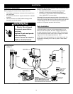
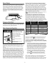
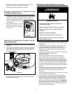
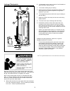
1. At least twice annually inspect the air intake chamber screen
(Figure 38) for any dust or debris that may have accumulated
on the louvers. NOTE: If the water heater is located in an
area that is subjected to lint and dirt, it may be necessary to
check the air intake chamber screen
more frequently.
2. Use a vacuum cleaner with a hose
attachment to remove any dust or
debris that may have accumulated
on the screen.
FIGURE 38.
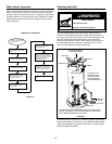
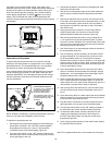
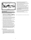
Cleaning the Combustion Chamber and Air
Diverter Assembly
1. Follow procedure outlined in “Removing the Manifold/Burner
Assembly”.
2. Use a vacuum cleaner/shop vac to remove all loose debris in
the combustion chamber (Figure 39). Use compressed air to
clear any dust or debris that may have accumulated on the
air diverter assembly.
FIGURE 39.
3. Reassemble following the procedure under “Replacing the
Manifold/Burner Assembly”
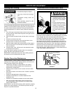
Replacing the Manifold/Burner Assembly
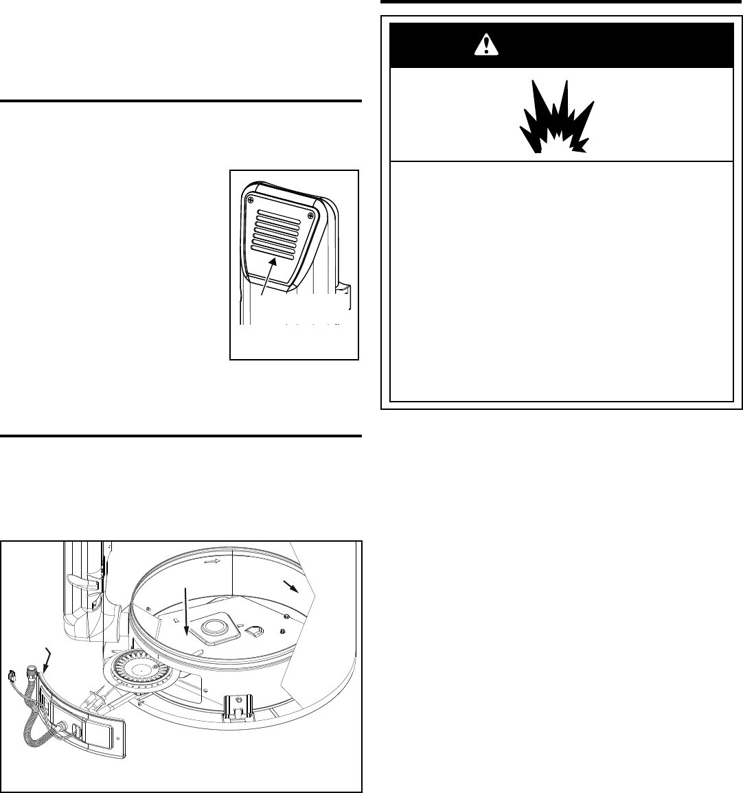
WARNING
Explosion Hazard
•
Ti
ghten both manifold door screws securely
.
•
Remove any fiberglass between gasket and
combustion chambe
r.
•
Replace viewport if glass is missing or damaged.
•
Replace two piece wire connector if missing or
removed.
•
Replace door gasket if damaged.
• Failure to follow these instructions can result in
death, explosion, or fire.
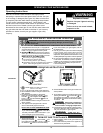
1. Check the door gasket for damage or imbedded debris prior
to installation.
2. Inspect the view port for damage and replace as required.
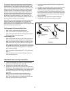
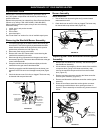
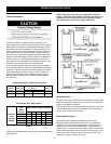
3. Insert the manifold/burner assembly into the burner
compartment making sure that the tip of the manifold tube
engages in the slot of the bracket inside the combustion
chamber (Figure 40).
4. Inspect the door gasket and make sure there is no fiberglass
insulation between the gasket and the
combustion chamber.
5. Replace the two screws, which secure the manifold/
burner assembly door to the combustion chamber and
tighten securely. Once the manifold/burner assembly door
is tightened, visually inspect the door gasket between the
manifold/burner assembly door and the combustion chamber
for spaces or gaps that would prevent a seal. IMPORTANT:
Do not operate the water heater if the door gasket does not
create a seal between the manifold door and the combustion
chamber.
6. During the following procedure, do not cross-thread or apply
any thread sealant to any of the fittings listed below. First,
reconnect the manifold tubing to the gas control valve/
thermostat.
7. Reconnect the flame sense/hot surface igniter wire to the gas
control valve/thermostat (Figure 35).
8. Turn gas supply on and refer to the Lighting Instructions.
9. With the burner lit, check the gas control valve/thermostat
supply line, two piece wire connector, and manifold tube
connections for leaks. Check for leaks by brushing on an
approved noncorrosive leak detection solution. IMPORTANT:
Do Not splash solution onto the electrical connections.
Bubbles forming indicate a leak. Correct any leak found. All
leaks must be fixed immediately.
Air Intake Chamber
Screen
Air Diverter
Assembly
Combustion
Chamber
Manifold
Door Gasket