28
3. Disconnect the electric connection by unplugging the water
heater from the wall outlet.
4. Shut off the incoming water supply to the water heater and
open a nearby hot water faucet to depressurize the water
tank.
5. Remove the manifold cover outer door and connect a hose
to the drain valve and terminate it to adequate drain or to the
exterior of the building. Open the drain valve and allow at
least 5 gallons of water from the tank to drain. Close drain
and remove hose.
6. Unplug the electrical connection on top of the powered
anode by pulling the wire connector up and off of the
powered anode rod electrical connector (Figure 33).
7. Remove the powered anode rod by using a ratchet and a
1-
1
/16” socket turning counterclockwise (Figure 33) (Note:
Figure 33 is shown exploded). If the socket used is short well
you may have to remove the top male connector first before
removing the powered anode rod.
8. Use Teflon
®
tape or an approved pipe sealant on threads of
the new powered anode rod.
9. Prior to installing, it will be necessary to use pliers to bend
up approximately 90° the electrical male connector on the
top of the powered anode rod. The electrical connector
should be bent upward in order to allow the 1-1/16” deep well
socket to pass over the connector. Note: if using a short well
socket the male connector must first be removed (Figure 33
is shown exploded for clarity).
10. Place the powered anode rod in the spud (top of the tank)
and turn clockwise until the threads are hand tight. Using a
ratchet and 1-
1
/16” socket tighten down water tight (Torque
should be between 65 to 120 foot pounds).
11. Open a nearby hot water faucet to purge air from the water
line. Fill water heater tank completely (Note: To assure the
water heater tank is full, keep the hot water faucet open for 3
minutes after a constant flow of water is obtained).
12. After turning off the hot water faucet, check for water leaks
around powered anode rod and immediately correct any if
found.
13. Upon determining there’s no water leak at the newly installed
powered anode rod, reconnect the electrical plug connector
to the top of the anode male terminal.
14. Plug the electric transformer in the wall outlet and turn the
gas supply back on to the gas control valve/thermostat.
15. Turn the gas control switch to the “ON” position (located on
the side of the gas control valve/thermostat (Figure 28).
16. To restart the water heater, follow the directions on the
“Lighting and Operating Instructions” label located on
the front of the water heater near the gas control valve/
thermostat (Figure 28).
17. Upon verifying proper operation of the water heater, replace
the manifold cover outer door.
TEFLON
®
is a registered trademark of E.I. Du Pont De Nemours and Company
may satisfy your normal hot water needs. If hot water use is
expected to be more than normal, a higher thermostat setting may
be required to meet the increased demand. When leaving your
home for extended periods (vacations, etc.) Set the electronic
control display temperature “COOLER” button to its lowest
setting. This will maintain the water at low temperatures with
minimum energy losses and prevent the tank from freezing during
cold weather.
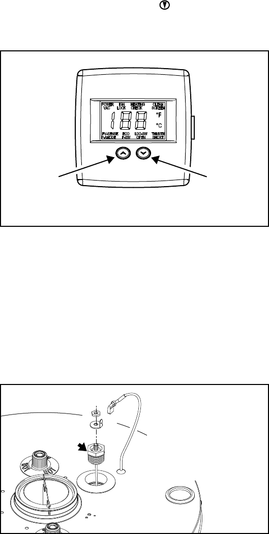
FIGURE 32.
Powered Anode Operation
To protect the glass-lined water tank from corrosion through
electrolysis, this water heater is equipped with a non sacrificial
powered anode rod. The powered anode rod is non sacrificial
and should not need to be replaced unless damaged.
If the powered anode rod has been damaged then the powered
anode rod should be removed from the water heater tank and
replaced. IMPORTANT: If the damaged powered anode rod has
not been replaced but has been removed permanently, this will
void any warranties.
FIGURE 33.
NOTE: Whether re-installing or replacing the powered anode rod,
check for any leaks and immediately correct if found.
To replace the powered anode rod:
1. Set the gas control valve/thermostat to its lowest setting by
pressing the “COOLER” and “HOTTER” buttons together
at the same time holding for 1 second. Then press the
“COOLER” button to the lowest setting (Figure 32).
2. Turn gas control switch to the “OFF” position (located right
side of the gas control valve/thermostat (Figure 28), and turn
off the gas supply to the unit.
Gas Control Valve/Thermostat Settings
COOLER
HOTTER
Electronic Control Display
Powered
Anode
Rod
Powered Anode System
To ensure a long, trouble-free
operating life, this water
heater is equipped with a
powered anode system.
The powered anode rod is of
a permanent design and does
not need replacing unless
damaged.


