


17
• Areadilyaccessiblemanualshutoffvalveinthegassupply
line serving the water heater, and
• Adripleg(sedimenttrap)aheadofthegascontrolvalvetohelp
prevent dirt and foreign materials from entering gas control valve.
• Aexiblegasconnectororagroundjointunionbetweenthe
shut off valve and control valve to permit servicing of the unit.
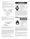
Be sure to check all the gas piping for leaks before lighting the
water heater. Use a soapy water solution, not a match or open
ame.Rinseoffsoapysolutionandwipedry.
The minimum inlet gas pressure shown on the rating plate is that
whichwillpermitringattheratedinput.
Water heaters covered in this manual have been tested and approved
for installation at elevations up to 7,700 feet (2,347 m) above sea
level.Forinstallationabove7,700feet(2,347m),thewaterheater’s
Btu input should be reduced at the rate of 4 percent for each 1,000
feet (305 m) above sea level which requires replacement of the
burneroriceinaccordancewiththeNationalFuelGasCode
ANSI Z223.1/NFPA 54. Contact your local gas supplier for further
information.
Failuretoreplacethestandardoricewiththeproperhighaltitude
oricewheninstalledatelevationsabove7,700feet(2,347m)
couldresultinimproperandinefcientoperationoftheappliance,
producing carbon monoxide gas in excess of the safe limits. This
could result in serious injury or death. Contact your local gas supplier
foranyspecicchangesthatmayberequiredinyourarea.
The appliance and its gas connection must be leak tested before
placing the appliance in operation.
The appliance and its individual shut-off valve should be
disconnected from the gas supply piping system during any
pressure testing of that system at test pressures in excess of 1/2
pound per square inch (3.5 kPa). It should be isolated from the
gas supply piping system by closing its individual manual shut-off
valve during any pressure testing of the gas supply piping system
at test pressures equal to or less than 1/2 pound per square inch
(3.5 kPa).
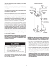
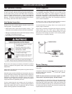
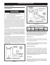
Connecting the gas piping to the gas control valve of the water
heater can be accomplished by either of the two methods shown
in Figures 20 and 21.
SedimentTraps
Contaminants in the gas lines may cause improper operation of
thegascontrolvalvethatmayresultinreorexplosion.Before
attaching the gas line be sure that all gas pipe is clean on the
inside. To trap any dirt or foreign material in the gas supply line, a
drip leg (sometimes called a sediment trap) must be incorporated
in the piping. The drip leg must be readily accessible. Install in
accordance with the Gas Piping section. Refer to the current
edition of the National Fuel Gas Code, ANSI Z223.1/NFPA 54.
A sediment trap should be installed as close to the inlet of the
water heater as practical at the time of water heater installation. The
sedimenttrapshouldbeeitherateettingwithacappednipplein
the bottom outlet or other device recognized as an effective sediment
trap.Ifateettingisused,itshouldbeinstalledinconformancewith
one of the methods of installation, shown in Figures 20 and 21.
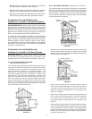
FIGURE 20. GAS PIPING WITH FLEXIBLE CONNECTOR.
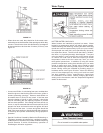
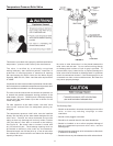
FIGURE 21. GAS PIPING WITH ALL
BLACK IRON PIPE TO GAS CONTROL.