


13
This water heater should not be connected to any heating
systems or component(s) used with a non-potable water
heating appliance.
All piping components connected to this unit for space
heating applications should be suitable for use with
potable water.
Toxic chemicals, such as those used for boiler treatment should
not be introduced into this system.
Water supply systems may, because of such events as high
line pressure, frequent cut-offs or the effects of water hammer
among others, have installed devices such as pressure
reducingvalves,checkvalves,backowpreventers,etc.to
control these types of problems. When these devices are not
equipped with an internal by-pass, and no other measures are
taken, the devices cause the water system to be closed. As
water is heated, it expands (thermal expansion) and closed
systems do not allow for the expansion of heated water.
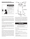
The water within the water heater tank expands as it is heated
and increases the pressure of the water system. If the relieving
pointofthewaterheater’stemperature-pressurereliefvalve
is reached, the valve will relieve the excess pressure. The
temperature-pressurereliefvalveisnotintendedforthe
constantreliefofthermalexpansion. This is an unacceptable
condition and must be corrected. It is recommended that any
devices installed which could create a closed system have a
by-pass and/or the system have an expansion tank to relieve the
pressure built by thermal expansion in the water system. Refer
to the Thermal Expansion section under Troubleshooting Guide
or contact local plumbing authority or local Sears Service Center
on how to control this situation.
NOTE: Toprotectagainstuntimelycorrosionofhotandcold
waterttings,itisstronglyrecommendedthatdi-electric
unionsorcouplingsbeinstalledonthiswaterheaterwhen
connectedtocopperpipe.
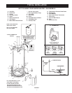
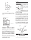
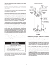
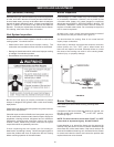
Figure 16 shows the typical attachment of the water piping to
the water heater. The 74-gallon model water heater is equipped
with1”NPTwaterconnections.
TYPICAL INSTALLATION
FIGURE 16.
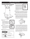
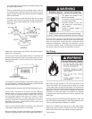
NOTE:Ifusingcoppertubing,soldertubingtoanadapter
beforeattachingtheadaptertothewaterconnections.Do
notsolderthewaterlinesdirectlytothewaterconnections
onthetank.Itwillharmthediptubeanddamagethetank.
• Lookatthetopcoverofthewaterheater.Thewateroutletis
marked“HOT”.Puttwoorthreeturnsofteontapearound
the exposed end of the NPT threaded nipple. Connect the hot
water pipe to the hot water outlet on the water heater. Please
note that adapters may be needed to match existing piping.
• Lookatthetopofthewaterheater.Thecoldwaterinlet
ismarked“COLD”.Puttwoorthreeturnsofteontape
around the exposed end of the NPT threaded nipple.
Connect the cold water pipe to the cold water inlet of the
water heater. Please note that adapters may be needed
to match existing piping.
NOTE: Thiswaterheaterissuperinsulatedtominimize
heatlossfromthetank.Furtherreductioninheatloss
canbeaccomplishedbyinsulatingthehotwaterlines
fromthewaterheater.