


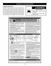
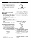
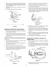
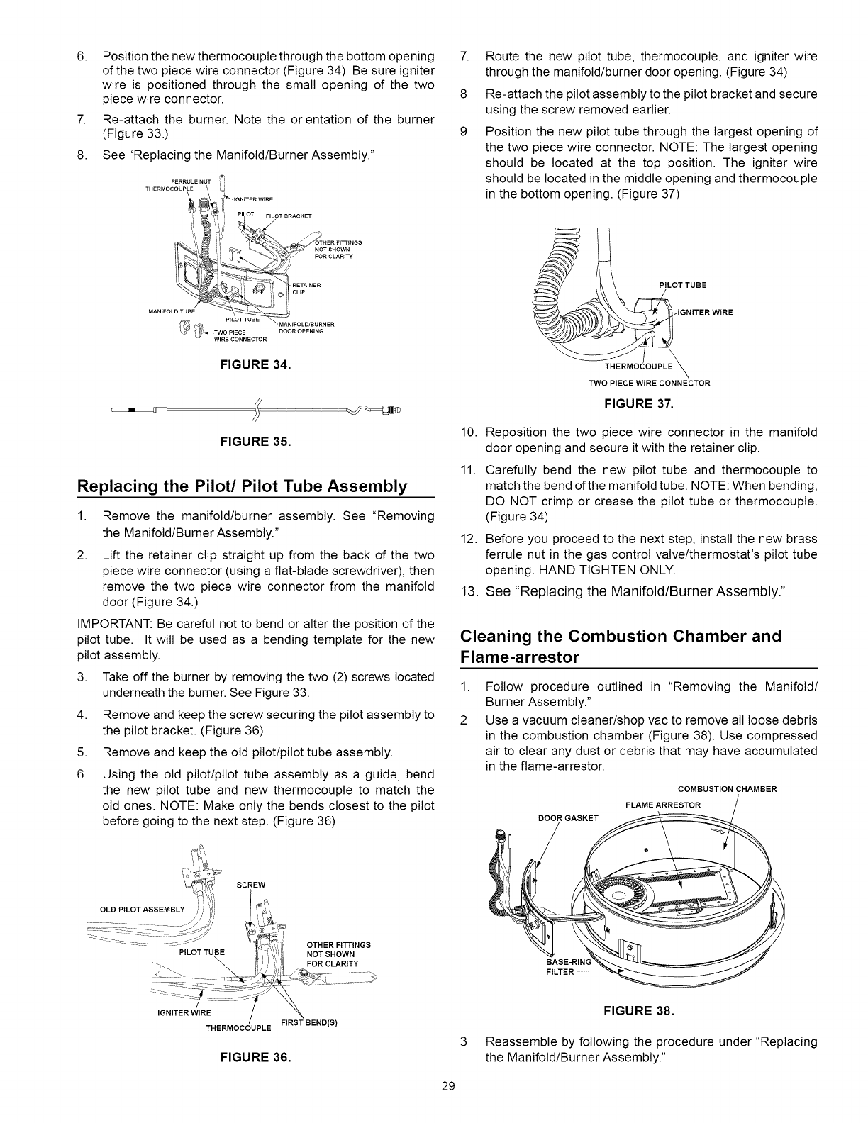
6. Position the new thermocoupte through the bottom opening
of the two piece wire connector (Figure 34). Be sure igniter
wire is positioned through the small opening of the two
piece wire connector.
7. Re-attach the burner. Note the orientation of the burner
(Figure 33.)
8. See "Replacing the Manifold/Burner Assembly."
FERROLENUTil
IGNITER WIRE
:' i!
PILOT PILOT BRACKET
',,, _ OTHER FITTINGS
_i""L ii C."- _ _,. NOT.......SHOWN
_ _] RETAINER
P LC T" UE E _ MANIFOLD/BU RNER
(_ t_T_ IWFOEPc_EoCN_..... D ..........
FIGURE 34.
FIGURE 35.
Replacing the Pilot/Pilot Tube Assembly
1.
Remove the manifold/burner assembly. See "Removing
the Manifold/Burner Assembly."
2. Lift the retainer clip straight up from the back of the two
piece wire connector (using a flat-blade screwdriver), then
remove the two piece wire connector from the manifold
door (Figure 34.)
IMPORTANT: Be careful not to bend or alter the position of the
pilot tube. It will be used as a bending template for the new
pilot assembly.
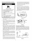
3. Take off the burner by removing the two (2) screws located
underneath the burner. See Figure 33.
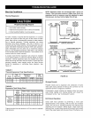
4. Remove and keep the screw securing the pilot assembly to
the pilot bracket. (Figure 36)
5. Remove and keep the old pilot/pilot tube assembly.
6.
Using the old pilot/pilot tube assembly as a guide, bend
the new pilot tube and new thermocouple to match the
old ones. NOTE: Make only the bends closest to the pilot
before going to the next step. (Figure 36)
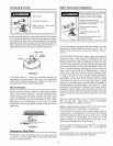
SCREW
PILOTTUBE
OTHER FITTINGS
NOT SHOWN
FOR CLARITY
7.
8.
9.
Route the new pilot tube, thermocoupte, and igniter wire
through the manifold/burner door opening. (Figure 34)
Re-attach the pilot assembly to the pilot bracket and secure
using the screw removed earlier.
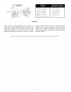
Position the new pilot tube through the largest opening of
the two piece wire connector. NOTE: The largest opening
should be located at the top position. The igniter wire
should be located in the middle opening and thermocouple
in the bottom opening. (Figure 37)
10.
11.
PILOT TUBE
IGNITER WIRE
THERMOCOUPLE
TWO PIECE WIRE CONNECTOR
FIGURE 37,
Reposition the two piece wire connector in the manifold
door opening and secure it with the retainer clip.
Carefully bend the new pilot tube and thermocoupte to
match the bend of the manifold tube. NOTE: When bending,
DO NOT crimp or crease the pilot tube or thermocouple.
(Figure 34)
12. Before you proceed to the next step, install the new brass
ferrule nut in the gas control valve/thermostat's pilot tube
opening. HAND TIGHTEN ONLY.
13. See "Replacing the Manifold/Burner Assembly."
Cleaning the Combustion Chamber and
Flame-arrestor
1.
2
Follow procedure outlined in "Removing the Manifold/
Burner Assembly."
Use a vacuum cleaner/shop vac to remove all loose debris
in the combustion chamber (Figure 38). Use compressed
air to clear any dust or debris that may have accumulated
in the flame-arrestor.
COMBUSTION CHAMBER
FLAME ARRESTOR
DOOR GASKET
BASE-RING
IGNITER WIRE
THERMOCOUPLE FIRST BEND(S)
FIGURE 36.
3.
FIGURE 38.
Reassemble by following the procedure under "Replacing
the Manifold/Burner Assembly."
29