


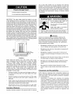
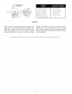
Closed System/Thermal Expansion
Property Damage Hazard
• AHwater heaters eventually !eak
• Do not install without adequate drainage,
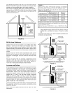
As water is heated, it expands (thermal expansion). In a closed
system, the volume of water will grow. As the volume of water grows,
there will be a corresponding increase in water pressure due to
thermal expansion. Thermal expansion can cause premature tank
failure (leakage). This type of failure is not covered under the limited
warranty. Thermal expansion can also cause intermittent temperature-
pressure relief valve operation: water discharged from the valve due
to excessive pressure build up. The temperature-pressure relief valve
is not intended for the constant relief of thermal expansion. This
condition is not covered under the limited warranty.
A properly sized thermal expansion tank should be installed
on all closed systems to control the harmful effects of thermal
expansion. Thermal expansion tanks are available from Sears
stores and through the Sears Service Centers. Contact the
local plumbing inspector, water supplier and/or the Sears
Service Center for assistance in controlling these situations.
(For additional information, see the Troubleshooting Guide later
in this manual.)
Temperature and Pressure Relief Valve
)f \
I
Explosion Harzard
Temperature-pressure relief
valve must comply with ANSI
Z21.22-CSA 4.4 and ASME
code.
• Properly sized temperature-
pressure relief valve must be
installed in opening provided.
• Can result in overheating
and excessive tank pressure.
• Can cause serious injury or
death.
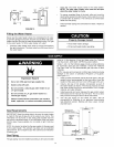
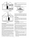
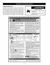
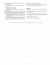
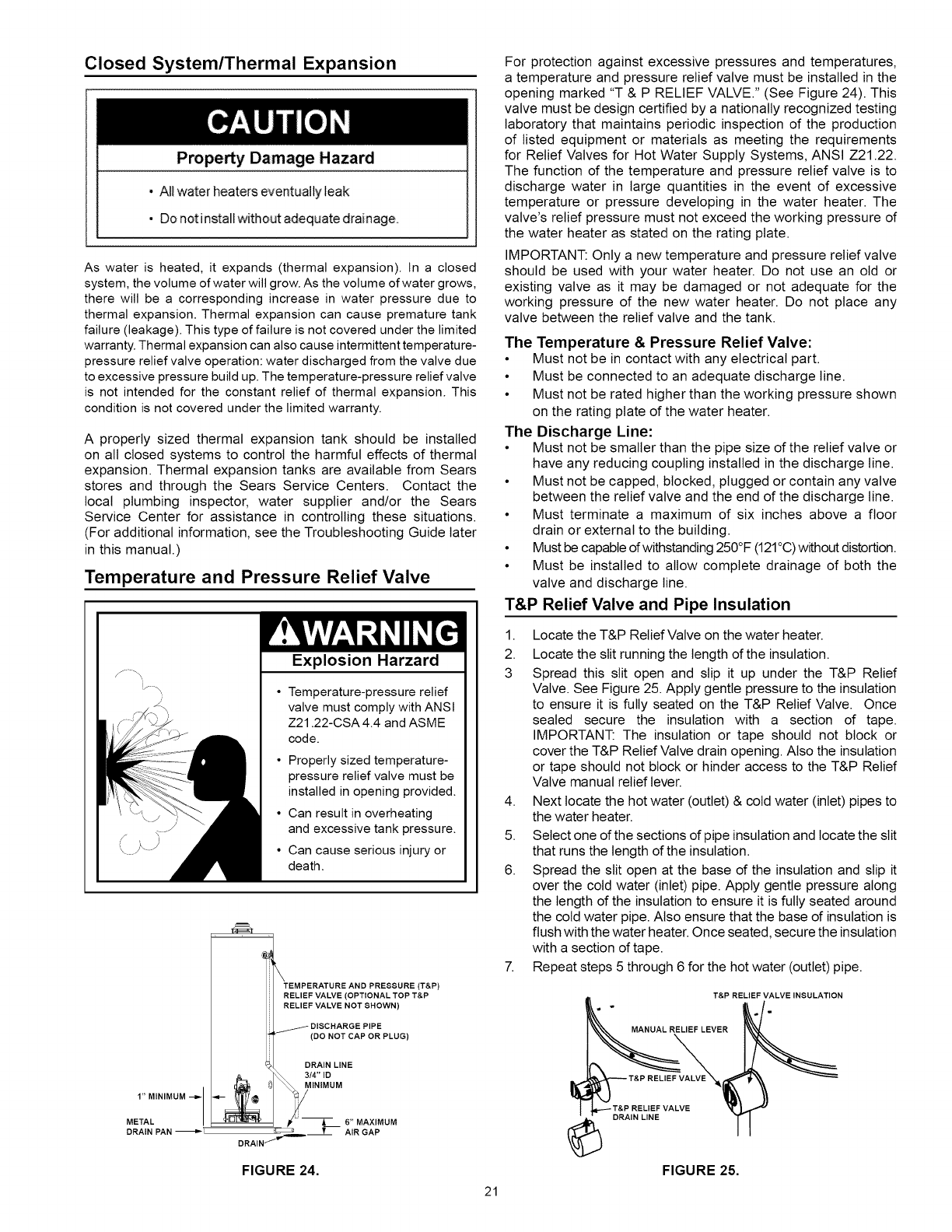
TEMPERATURE AND PRESSURE (T&P)
RELIEF VALVE (OPTIONAL TOP T&P
RELIEF VALVE NOT SHOWN)
DISCHARGE PIPE
(DO NOT CAP OR PLUG)
DRAIN LINE
3/4" ID
1" MINIMUM --_ _,-_;;_ %/AINIMUM
METAL __l,I q,lU "_'r_ p/_-- 6" MAXIMUM
DRAIN PAN %_'_-- AIR GAP
DRAIN _
FIGURE 24.
For protection against excessive pressures and temperatures,
a temperature and pressure relief valve must be installed in the
opening marked "T & P RELIEF VALVE." (See Figure 24). This
valve must be design certified by a nationally recognized testing
laboratory that maintains periodic inspection of the production
of listed equipment or materials as meeting the requirements
for Relief Valves for Hot Water Supply Systems, ANSI Z21.22.
The function of the temperature and pressure relief valve is to
discharge water in large quantities in the event of excessive
temperature or pressure developing in the water heater. The
valve's relief pressure must not exceed the working pressure of
the water heater as stated on the rating plate.
IMPORTANT: Only a new temperature and pressure relief valve
should be used with your water heater. Do not use an old or
existing valve as it may be damaged or not adequate for the
working pressure of the new water heater. Do not place any
valve between the relief valve and the tank.
The Temperature & Pressure Relief Valve:
• Must not be in contact with any electrical part.
• Must be connected to an adequate discharge line.
• Must not be rated higher than the working pressure shown
on the rating plate of the water heater.
The Discharge Line:
• Must not be smaller than the pipe size of the relief valve or
have any reducing coupling installed in the discharge line.
• Must not be capped, blocked, plugged or contain any valve
between the relief valve and the end of the discharge line.
• Must terminate a maximum of six inches above a floor
drain or external to the building.
• Must be capable ofwithstanding 250°F (121°C)without distortion.
• Must be installed to allow complete drainage of both the
valve and discharge line.
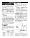
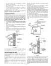
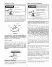
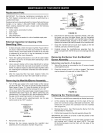
T&P Relief Valve and Pipe Insulation
1. Locate the T&P Relief Valve on the water heater.
2. Locate the slit running the length of the insulation.
3 Spread this slit open and slip it up under the T&P Relief
Valve. See Figure 25. Apply gentle pressure to the insulation
to ensure it is fully seated on the T&P Relief Valve. Once
sealed secure the insulation with a section of tape.
IMPORTANT: The insulation or tape should not block or
cover the T&P Relief Valve drain opening. Also the insulation
or tape should not block or hinder access to the T&P Relief
Valve manual relief lever.
4. Next locate the hot water (outlet) & cold water (inlet) pipes to
the water heater.
5. Select one of the sections of pipe insulation and locate the slit
that runs the length of the insulation.
6. Spread the slit open at the base of the insulation and slip it
over the cold water (inlet) pipe. Apply gentle pressure along
the length of the insulation to ensure it is fully seated around
the cold water pipe. Also ensure that the base of insulation is
flush with the water heater. Once seated, secure the insulation
with a section of tape.
7. Repeat steps 5 through 6 for the hot water (outlet) pipe.
T&P RELIEF VALVE INSULATION
MANUAL RELIEF LEVER
©
DRAIN LINE
FIGURE 25.
21