


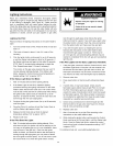
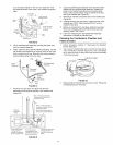
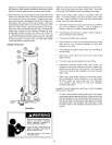

asabendingtemplateforthenewpilotassembly.Note
theplacement/orderofthewiresinthemanifoldcomponent
block.
Thermopile
Connector _e
Igniter j_-
Wire i%'
Mantfot!
Component
Block_
Pitot/Thermopite
Assembly Screw
Burneran other
:_?_i_ fittingsnotshow
_;':_ for clarity.
-- Red
Wire
5,
6.
FIGURE 36.
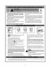
Lift the pitot/thermopite assembly (including the igniter wire)
from the manifold assembly.
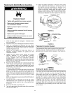
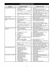
NOTE: Read this step carefully before proceeding. Use the
old pilot/pilot tube assembly as a guide, bend the new pilot
tube to match the old one. Make only the bends closest to
the pilot before going to the next step.
_ile
pile
Connector Assembly
Thermal
Switch
Wire
7,
FIGURE 37.
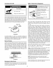
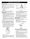
Route the new pilot tube, new igniter wire and new
thermopite wire through the opening in the manifold door
(Figure 38).
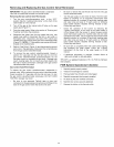
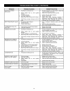
Manifold
Component
Block _
/
Igniter Wire Passes
through Center of
Manifold Component
Block (Smallest Hole)
Pilot Tube passes
through Bottom Hole
of Manifold Component
Block (Largest Hole)
Red (+) Thermal Switch Wire
Connects to the Gas Control
Valve\Thermostat.
White (-) Thermopile Wire
Connects to the Gas Control
Valve\Thermostat.
Red Thermal Switch Wires
Connection at Manifold Door
W
\Thermopile Wires pass
through Top Hole of
Manifold Component
Block
FIGURE 38.
8. Using the pilot/thermopite assembly screw removed earlier
reattach the new pitot/thermopite assembly. Reattach the
bumer to the manifold using the screws removed earlier.
NOTE: make sure the burner scoop is oriented to the pilot
side of the manifold tube (Figure 35).
9. Reinstall the manifold component block in the manifold door
(Figure 38).
10. Carefully bend the new pilot tube to match the bend of the
manifold tube. NOTE: When bending DO NOT crimp or
crease the pilot tube.
11. Before you proceed to the next step, install the new brass
ferrule nut in the gas control valve/thermostat's pilot tube
opening. HAND TIGHT ONLY.
12. Follow the "Replacing the Burner/Manifold Assembly"
instructions to replace the manifold door.
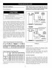
Cleaning the Combustion Chamber and
Flame-arrestor
1,
2.
Follow procedure outlined in "Removing the Manifold/
Burner Assembly."
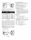
Use a vacuum cleaner/shop vac to remove all loose debris
in the combustion chamber (Figure 39). Use compressed
air to clear any dust or debris that may have accumulated
in the flame-arrestor.
COMBUSTION CHAMBER
FLAMEARRESTOR
DOOR GASKET
3,
BASE-RING
FILTER
FIGURE 39.
Reassemble by following the procedure under "Replacing
the Manifold/Burner Assembly."
31