


Replacement Parts
IMPORTANT: The following maintenance procedures are for
the FVIR System components and should be performed by a
qualified technician.
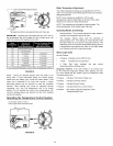
Replacement parts may be ordered from Sears Parts and
Service Centers or by calling 1-800-4-MY-HOME (1-800-469-
4663). When ordering replacement parts, always have the
following information ready:
1. model, serial, and product number
2. type of gas
3. item number
4. parts description
See the Parts Order List section for a list of available repair parts.
External Inspection & Cleaning of the
Base-Ring Filter
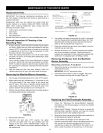
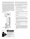
1. At least annually, check the base-ring filter (Figure 39) for
any dust or debris that may have accumulated on the filter
screen. NOTE: If the water heater is located in an area that
is subjected to tint and dirt, it may be necessary to check
the base-ring filter more frequently.
2. Follow the Lighting Instructions to turn off the water heater
and allow it to coot for 10 minutes before attempting to clean
the base-ring filter.
3. Use a vacuum cleaner with a hose attachment to remove
any dust or debris that may have accumulated on the filter.
NOTE: If unable to inspect or clean the base-ring filter, follow
the "Cleaning the Combustion Chamber and Flame-arrestor"
instructions.
4. After the base-ring filter has been cleaned, follow the
Lighting Instructions to return the water heater to service.
Removing the Manifold/Burner Assembly
1. Turn the gas control/temperature knob to the "OFF" position.
2. Before performing any maintenance, it is important to turn
off the gas supply to the water heater at the manual gas
shut-off valve. This valve is typically located beside the
water heater. Note the position of the shut-off valve in the
open/on position then proceed to turn it off (Figure 11).
3. With the unit shut-off allow sufficient time for the water heater to
cool before performing any maintenance.
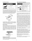
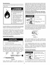
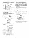
Ignite__S
Butte irtee
Ignlter_" _qi [_ "
• i_ _@i, I, (Rght
Lead n % _ ,i'_ Side)
Wire U /4 _ _._J
[]J Pilot / Red Wire
Igniter_,..t.. Tube ] (Left Side)
Wire ...._ M_eifold Tube
4,
5.
FIGURE 33.
Remove the outer door.
Disconnect the pilot tube (7/16" wrench), the igniter
wire from the igniter lead wire, and manifold tube (3/4"
wrench) at the gas control valve/thermostat. (Figure 33).
NOTE: L.R Gas systems use reverse (left-hand) threads on
the manifold tube.
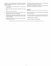
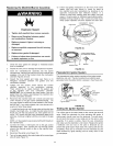
GAS CONTROL VALVE/THERMOSTAT THERMOPILE AND
GAS CONTROL/
TEMPERATURE
PIEZOIGNITER BUTTON
CONNECTIONS
PILOT TUBE
VIEWPORT
OUTER DOOR]
NOT SHOWN J
-MANIFOLD TUBE
-THERMALSWITCH
MANIFOLD SCREW (2) --
MANIFOLD COMPONENT BLOCK
FIGURE 34.
6. Use needle nose pliers to disconnect the white (-) thermopile
wire from the gas control valve/thermostat (Figure 33). Then
disconnect both red thermal switch wires from the thermal
switch on the old manifold door. (Figure 34).
7. Grasp the manifold tube and push down slightly to free the
manifold tube and pilot tube.
8. Remove the screws (1/4" nut driver) securing the manifold
door to the combustion chamber. Carefully remove the
manifold door assembly from the combustion chamber. BE
SURE NOT TO DAMAGE ANY INTERNAL PARTS.
Removing the Burner from the Manifold/
Burner Assembly
Natural Gas (Low Nox) & L.P. Gas Burner
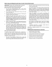
1. Take off the burner by removing the two (2) screws located
underneath the burner.
IMPORTANT: DO NOT remove the orifice.
2. Check the burner to see if it is dirty or clogged. The burner
may be cleaned with soap and hot water (Figure 35).
3O
(BOTTOM VIEW)
SCREW_
BURNER
(BOTTOM VIEW)
FIGURE 35.
Replacing the Pilot/Thermopile Assembly
1. Follow the "Removing the Burner/Manifold Assembly"
instructions on the following pages to remove the manifold
door assembly.
2. Natural Gas/LP Models - Remove the burner to access the
pitot/thermopite assembly. Remove and keep the screws
securing the burner to the manifold (Figure 35).
3. Remove the screw securing the pilot/thermopile assembly to
the pilot bracket and keep for reuse later.
4. Lift the retainer clip straight up from the back of the
manifold component block (using a flat-blade screwdriver),
then remove the manifold component block from the
manifold door (Figure 36). IMPORTANT: Be careful not to
bend or alter the position of the pilot tube, it will be used