


21
Removing the Burner Door Assembly
1. Turn off the gas to the water heater at the manual gas
shut-off valve (Figure 3).
2. Turn the gas control knob on the combination gas control
valve/thermostat clockwise to the “OFF” position (Figure 1).
NOTE: Depress the dial stop on Robertshaw valve before
turning the gas control knob. See Lighting Instructions on
the water heater.
3. Remove the outer door.
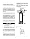
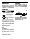
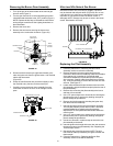
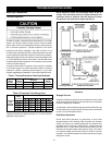
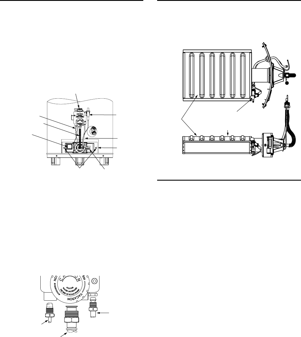
4. Remove the two screws securing the burner door
assembly to the combustion chamber. (Figure 24).
GAS VALVE/
THERMOSTAT
THERMOCOUPLE
MANIFOLD
TUBE
VIEWPORT
DOOR
SCREW (2)
TWO PIECE WIRE
CONNECTOR
PILOT
TUBE
BURNER
DOOR
PIEZO
IGNITER
BUTTON
FIGURE 24.
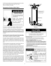
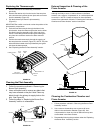
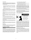
5. Disconnect the thermocouple (right-hand thread), pilot
tube, the igniter wire from the igniter button, and manifold
tube at the thermostat.
(Figure 25).
6. Grasp the manifold tube and push down slightly to free
the manifold tube, pilot tube, and thermocouple.
7. Carefully remove the burner door assembly from the
combustion chamber. Be sure not to damage internal
parts.
ROBERTSHAW GAS VALVE
THERMOCOUPLE
MANIFOLD TUBE
PILOT TUBE
FIGURE 25.
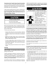
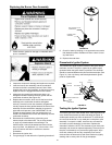
Ultra Low NOx Natural Gas Burner
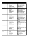
Check the burner to see if it is dirty or clogged. The burner
may be cleaned with soft paint brush (Figure 26). Do not use
a wire brush or any tool that may damage the burner screen.
Important: Do not use the burner if the burner screen is
damaged. NOTE: Damage may be rips or holes in the burner
screen. Discoloration is normal.
BURNER
PILOT ASSEMBLY
USE BRUSH ON THIS SURFACE
FIGURE 26.
Replacing the Pilot Assembly
1. Follow the instructions in “Removing the Burner Door
Assembly” section to remove the assembly.
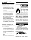
2. Remove the retainer clip securing the two piece wire
connector to the burner door assembly. (Note the orientation
of the retainer clip). Insert the tip of a large flat head
screwdriver between the clip and the top of the two piece
wire connector. Carefully rotate the screwdriver to raise the
clip. It may be necessary to remove the connector one side
at a time. (See Figure 27.)
3. Locate where the thermocouple connects to the rear of the
pilot assembly, and pull the thermocouple tip from the rear of
the pilot assembly.
4. Remove the nut securing the pilot assembly to the burner
and keep it for reuse later.
5. Use a 1/2” open end wrench, to loosen the nut securing the
pilot tube to the pilot. To prevent any bending use a pair of
pliers to steady the pilot bracket.
6. Remove the old pilot assembly (including the igniter wire)
from the burner door assembly.
7. Insert the pilot tube into the new pilot assembly. Important:
The new pilot assembly comes with an orifice. This orifice
must be installed when replacing the pilot assembly.
IMPORTANT: Do not operate this water heater without the
orifice in place.
8. Use a 1/2” open end wrench, to tighten the nut securing the
pilot tube to the pilot. To prevent any bending use a pair of
pliers to steady the pilot bracket.
9. Use the nut removed in a previous step to secure the new
pilot assembly to the burner.
10. Insert the igniter wire through the burner door and reconnect
the thermocouple to the pilot assembly. See “Replacing the
Thermocouple” section.
11. Reinstall the two piece wire connector. NOTE: The pilot
tube must be at the top followed by the igniter wire then the
thermocouple.
12. Follow the instructions in “Replacing the Burner Door
Assembly” section to reinstall the assembly.