


13
This water heater shall not be connected to any heating
systems or component(s) used with a non-potable water heating
appliance.
All piping components connected to this unit for space heating
applications shall be suitable for use with potable water.
Toxic chemicals, such as those used for boiler treatment shall
not be introduced into this system.
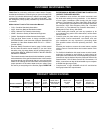
Water supply systems may, because of such events as high line
pressure, frequent cut-offs or the effects of water hammer, have
installed devices such as pressure reducing valves, check valves,
back fl ow preventers, etc. to control these types of problems.
When these devices are not equipped with an internal by-pass,
and no other measures are taken, the devices cause the water
system to be closed. As water is heated, it expands (thermal
expansion) and closed systems do not allow for the expansion
of heated water.
The water within the water heater tank expands as it is heated
and increases the pressure of the water system. If the relieving
point of the water heater’s temperature-pressure relief valve
is reached, the valve will relieve the excess pressure. The
temperature-pressure relief valve is not intended for the
constant relief of thermal expansion. This is an unacceptable
condition and must be corrected. It is recommended that any
devices installed which could create a closed system have a
by-pass and/or the system have an expansion tank to relieve the
pressure built by thermal expansion in the water system. Refer
to the Thermal Expansion section under Troubleshooting Guide
or contact local plumbing authority or local Sears Service Center
on how to control this situation.
NOTE: To protect against untimely corrosion of hot and cold
water fi ttings, it is strongly recommended that di-electric
unions or couplings be installed on this water heater when
connected to copper pipe.
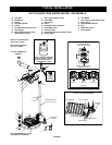
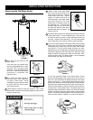
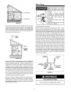
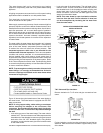
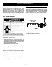
Figure 15 shows the typical attachment of the water piping to
the water heater. The water heater is equipped with 3/4” NPT
water connections.
NOTE: If using copper tubing, solder tubing to an adapter
before attaching the adapter to the cold water inlet
connection. Do not solder the cold water supply line directly
to the cold water inlet. It will harm the dip tube and damage
the tank.
• Look at the top cover of the water heater. The water outlet is
marked “HOT”. Put two or three turns of Tefl on tape around the
threaded end of the threaded-to-sweat coupling and around
both ends of the 3/4” NPT threaded nipple. Using fl exible
connectors, connect the hot water pipe to the hot water outlet
on the water heater.
TEFLON
®
is a registered trademark of E.I. Du Pont De Nemours and Company.
• Look at the top of the water heater. The cold water inlet is
marked “COLD”. Put two or three turns of Tefl on tape around
the threaded end of the threaded-to-sweat coupling and
around both ends of the 3/4” NPT threaded nipple. Using
fl exible connectors, connect the cold water pipe to the cold
water inlet of the water heater.
NOTE: This water heater is super insulated to minimize
heat loss from the tank. Further reduction in heat loss
can be accomplished by insulating the hot water lines
from the water heater.
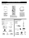
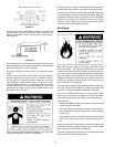
INSTALLATION COMPLETED USING
INSTALLATION KIT
T & P Valve and Pipe Insulation
Remove insulation for T & P valve and pipe connections from
carton.
FIGURE 15A.
Fit pipe insulation over the incoming cold water line and the hot
water line. Make sure that the insulation is against the top cover
of the heater.
FLOOR DRAIN
DISCHARGE PIPE
(Do not cap or plug)
TEMPERATURE-
PRESSURE
RELIEF VALVE
3/4” THREADED
COUPLING
THREADED TO
SWEAT COUPLING
SHUTOFF
VALVE
FLEXIBLE
WATER
CONNECTORS
3/4” THREADED
COUPLING
THREADED TO
SWEAT COUPLING
DRAFT HOOD
HOT WATER
OUTLET
COLD WATER
INLET
6” MAXIMUM
AIR GAP
FIGURE 15.