


Installation Instructions (cont'd)
Temperature-Pressure
Relief Valve
AWARNING
At the time of manufacturethiswater heaterwasprovided
with a combinationtemperature-pressuresrelief valvecer-
tified by a nationally recognized testing laboratory that
maintainsperiodic inspectionof productionof listedequip-
ment or materials, as meeting the requirements for Relief
Valvesand Automatic Gas Shutoff Devicesfor Hot Water
SupplySystems,and the latest edition ofANSI Z21.22 and
the code requirements of ASME. If replaced, the valve
must meet the requirements of local codes,but not less
than a combination temperature and pressurerelief valve
certified asmeeting the requirements for ReliefValvesand
Automatic Gas Shutoff Devices for Hot Water Supply
Systems,ANSI Z21.22 by a nationally recognized testing
laboratory that maintainsperiodicinspectionof production
oflistedequipment or materials.
The valve must be marked with a maximum set pressure
not to exceedthe marked hydrostaticworking pressureof
the water heater (150 Ibs./sq.in.) and a dischargecapacity
not lessthan the water heater inputrate asshownon the
model rating plate. (Electric heaters - watts divided by
1000x 3415 equalBTU/Hr. rate.)
Yourlocaljurisdictionalauthority, while mandatingthe use
of a temperature-pressure relief valve complying with
ANSI Z21.22 and ASME, may require a valvemodel differ-
entfrom the onefurnishedwith the water heater.
Compliancewith suchlocalrequirements must besatisfied
_)ythe installer or end user of the water heater with a
locally prescribed temperature-pressure relief valve
installedin the designatedopening in the water heater in
placeofthe factory furnishedvalve.
For safe operation of the water heater, the relief valve
must not be removed from it's designated opening or
plugged.
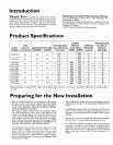
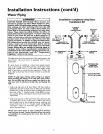
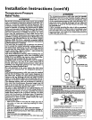
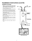
The temperature-pressure relief valve must be installed
directly into the fitting of the water heater designatedfor
the relief valve. Positionthe valve downward and provide
tubingso that any dischargewill exit only within 6 inches
above,or at any distancebelowthe structuralfloor.Becer-
tein that no contact is made with any llve electrical part.
The dischargeopeningmust not be blockedor reduced in
size under any circumstances. Excessivelength, over 30
feet, or useof more than four elbowscan causerestriction
andreduce the dischargecapacityofthe valve.
No valveor other obstructionis to be placedbetween the
relief valveand the tank. Do not connecttubingdirectlyto
dischargedrain unlessa 6" air gap isprovided.To prevent
bodilyinjury,hazard to life,or property damage,the relief
valve must be allowed to discharge water in quantities
shouldcircumstancesdemand. If the dischargepipe is not
connected to a drain or other suitablemeans, the water
flowmay causeproperty damage.
The DischargePipe:
Must not be smaller in size than the outlet pipe size of
the valve, or have any reducing couplings or other
restriction.
Must not bepluggedor blocked.
Mustbe ofmaterial listedfor hot water distribution.
Must be installed so asto allow complete drainage of
both the temperature-pressure relief valve,andthe dis-
chargepipe.
Must terminate at an adequatedrain.
Must not have any valve between the relief valve and
tank.
_,WARNING
The temperature-pressure relief valve must be manually
operated at least once a year.Caution shouldbe taken to
ensure that (I) no one is in front of or around the outlet
of the temperature-pressure relief valve discharge line,
and (2) the water manuallydischargedwill not causeany
bodily injury or property damage becausethe water may
be extremely hot.
If after manuallyoperatingthe valve, it failsto completely
reset and continuesto release water, immediately, close
the coldwater inlet to the water heater,followthe drain-
ing instructions, and replace the temperature-pressure
relief valvewith a newone.
HOT
HOT
COLD
F_E-
PRESSURE
RELIEF VALVE
PIPE
(Do not cap or plug)
6" AIR GAP
FLOOR IN
T&PRELIEF
VALVE PROBE
TEMPERATURE-
PRESSURE
RELIEF VALVE
T&P
SHANK
NIPPLE 'LENGTH
• if ashorlshank (lessthan 2") temperature-pressulete_f valve isto be installed
(as shown),a nippleand couplin9 must be used¸
• Ffa longshank(2'or longer)isto be installed,do not use1henippleand coupling¸
lnstamTeroperature-Pr_ssureprotective_quipmentrequiredbylocalcodes,butnotless Ihana r_na-
t_onTemperature-PressureReliefValvecettitiedas meeting the requirementsforReliefVetvesand
AulomaticGasShutoffDev_.esforHol-WaterSupprySystems,ANSZ2122 bya natw_naltyre(_gn_edlesl-
inglabo_alOr/t_l maintainspeded_wv,pecti_ ofprod_ct_noflistedequigrnentor materials.The val_
mustbe onented,pTOVi_dwithlub_ng,oro_hen_memetailedsothatdr,ct_r;e canexilorgywtlhin6 red'as
above,or atanydslanCebelowlhe structuralIk_or,andcan,w_tcOnlaclanylivee_,cl_a!pall"
For_le operatK,nofIhewaterheater¸theReEf Vave mustnotbe removedorplugged¸ f
S_BrP_nL_I_leading. "TemperatUfe.p[assureReliefValve"for insta_al_Onandmai_lenaflceof Relie
Va)ve,diSChargeppe andothersafetyprecautions¸