


25
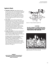
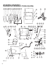
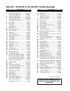
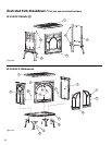
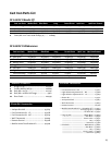
GF 100 DV II Nordic QT
GF 200 DV II Lillehammer
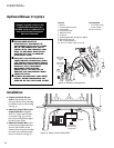
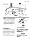
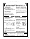
Blower Operation
The variable-speed blower will enhance heat circulation
around the firebox and out into the room. The blower is
controlled by a heat activated switch (snapstat) that
will ONLY function when the control switch is in AUTO
setting. After the fire has been burning for a time, the
snapstat will react to the heat and activate the blower.
Fan speed may be manually adjusted with the rheostat
knob. If the burner turns off, the blower will be shut off
automatically when the stove cools down.
If automatic blower circulation is not desired, place
the blower control switch in the MANUAL position.
M6 x 20 mm
Hex Bolts
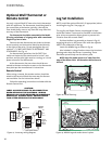
Figure 38. Blower Wiring Diagram
CAUTION:
LABEL ALL WIRES PRIOR TO DISCONNEC-
TION WHEN SERVICING CONTROLS. WIRING
ERRORS CAN CAUSE IMPROPER AND DAN-
GEROUS OPERATION.
VERIFY OPERATION AFTER SERVICING.
ATTENTION:
Au moment de l’entrentien des commandes,
etiquietez tous le fils avant le
debranchement. es erreurs de ceblage
peuvent entra tun fonctionnement inadequat
et dangereux.
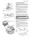
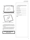
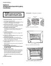
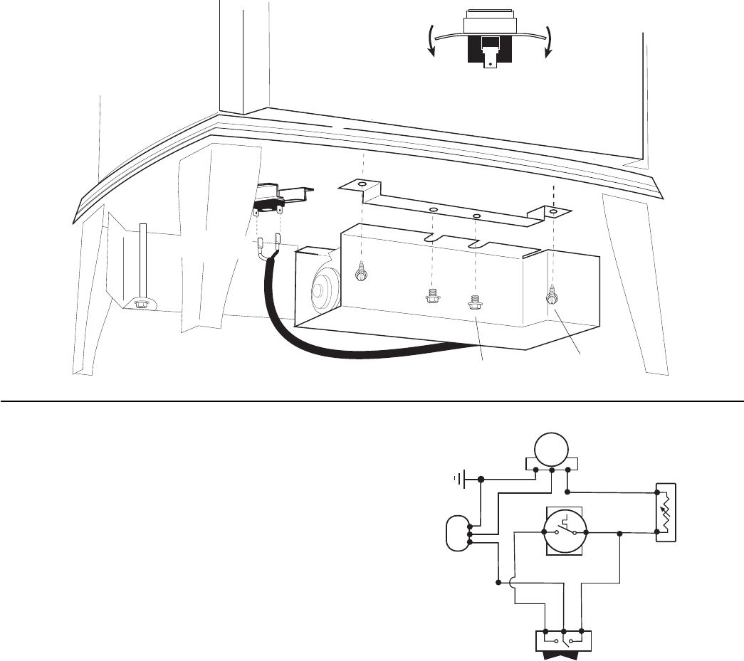
4. Attach the Blower to the stove.
GF 100 DV II: First install the Mounting Bracket to
the holes in the bottom of the rear shroud using
two #8 x 1/2” sheet metal screws. Then attach the
Blower to the Mounting Bracket using the two M6
flange head hex bolts as shown in fig. 35 and 37.
GF 200 DV II: Attach the Blower directly to the
tapped hole in the cast iron stove bottom using the
two M6 flange head hex bolts.
5. Attach either Snapstat wire connector to either
Snapstat terminal. See figs.35 and 37.
6. Connect power cord to the nearest outlet.
Snapstat
Connectors
Mounting Bracket
for GF100 DV II
#8 x 1/2” sheet
metal screws
Figure 37 . Attach Blower to
the stove bottom and
connect wires to Snapstat.
SNAPSTAT
BK
W
G
BLOWER
POWER
SUPPLY
W
RHEOSTAT
BK
BL
SWITCH
MANUAL OFF AUTO
GY
BK
W
G
BL
BK