


356485-UIM-G-1211
20 Johnson Controls Unitary Products
GAS PIPING LEAK CHECK
It is recommended that when the gas supply is first connected to the
furnace, the ground union be loosened until the odor of gas is detected.
When gas is detected, immediately tighten the union and check for gas
leaks. Allow five minutes for any gas to dissipate before continuing with
the start-up procedure. Be sure that proper ventilation is available to
dilute and carry away any vented gas.
With furnace in operation, check all of the pipe joints, gas valve connec-
tions and manual valve connections for leakage using an approved gas
detector, a non-corrosive leak detection fluid or other leak detection
methods. Take appropriate action to stop any leak. If a leak persists,
replace the faulty component.
The furnace and its equipment shut-off valve must be disconnected
from the gas supply during any pressure testing of that system at test
pressures in excess of 1/2 PSI (3.45 kPa).
The furnace must be isolated from the gas supply piping system by
closing the equipment shut-off valve during any pressure testing of the
gas supply system.
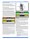
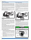
IGNITION SYSTEM SEQUENCE
1. Turn the gas supply ON at external valve and main gas valve.
2. Set the thermostat above room temperature to call for heat.
3. System start-up will occur as follows:
a. The induced draft blower motor will start and come up to
speed. Shortly after inducer start-up, the hot surface igniter
will glow for about 17 seconds.
b. After this warm up, the ignition module will energize (open)
the main gas valve.
c. After flame is established, the supply air blower will start in
about 30 seconds.
With furnace in operation, check all of the pipe joints, gas valve connec-
tions and manual valve connections for leakage using an approved gas
detector, a non-corrosive leak detection fluid, or other leak detection
methods. Take appropriate steps to stop any leak. If a leak persists,
replace the component.
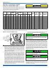
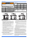
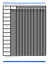
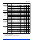
CALCULATING THE FURNACE INPUT
(NATURAL GAS)
Verify natural gas input rate by clocking meter.
1. Turn off all other gas appliances and pilots.
2. Run furnace for a minimum of 3 minutes in heating operation.
3. Measure time (in sec) for gas meter to complete 1 revolution and
note reading. The 2 cubic feet dial provides a more accurate mea-
surement of gas flow.
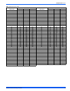
4. Refer to Table 10 for cubic feet of gas per hour.
5. Multiply cubic feet per hour by heating valve (BTU/cu ft) to obtain
input.
If clocked rate does not match the input rate from the unit nameplate.
follow steps in next section to adjust the manifold pressure. Repeat
steps 2 - 5 until correct input is achieved.
FIRE OR EXPLOSION HAZARD
Failure to follow the safety warnings exactly could result in serious
injury, death or property damage.
Never test for gas leaks with an open flame. Use a commercially
available soap solution made specifically for the detection of leaks
to check all connections. A fire or explosion may result causing
property damage, personal injury or loss of life.
Burner ignition may not be satisfactory on first startup due to resid-
ual air in the gas line or until gas manifold pressure is adjusted. The
ignition control will make three attempts to light before locking out.
Burner ignition may not be satisfactory on first startup due to resi-
dential air in the gas line or until gas manifold pressure is adjusted.
The ignition control will make 3 attempts to light before locking out.
Burner orifices are sized to provide proper input rate using natural
gas with a heating value of 1030 BTU/Ft
3
(38.4 MJ/m
3
). If the heat-
ing value of your gas is significantly different, it may be necessary
to replace the orifices.
If orifice hole appears damaged or it is suspected to have been
redrilled, check orifice hole with a numbered drill bit of correct size.
Never redrill an orifice. A burr-free and sqaurely aligned orifice hole
is essential for proper flame characteristics.
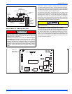
DO NOT bottom out gas valve regulator adjusting screw. This can
result in unregulated manifold pressure and result in excess over-
fire and heat exchanger failures.
DO NOT set manifold pressure less than 3.2 in wc or more than 3.8
in wc for natural gas at sea level. If manifold pressure is outside this
range, change main burner orifices.
Be sure to relight any gas appliances that were turned off at the
start of this input check.
NOTICE
NOTICE
NOTICE